Bitumen recovery process for oil sand

a technology of oil sand and bitumen, which is applied in the direction of sedimentation settling tanks, floating sedimentation devices, wet separation, etc., can solve the problems of less energy efficiency of the process and more maintenance of the moving parts, and achieve the effect of minimizing turbulen

Active Publication Date: 2007-04-26
BITMIN RESOURCES
View PDF38 Cites 21 Cited by
  • Summary
  • Abstract
  • Description
  • Claims
  • Application Information

AI Technical Summary

Benefits of technology

[0028] Unlike conventional froth flotation cells, column flotation cells do not use mechanical agitation. The absence of intense agitation is believed to promote selectivity and aid in the recovery of the bitumen. Generally speaking, in a column flotation cell, the feed material enters the column at at least one location, typically located in the upper third of a body of the column flotation cell. The feed material descends or travels downwardly through a bitumen collection zone or area towards a lower end of the column flotation cell. Concurrently, a swarm or mass of gas bubbles are generated which ascend or travel upwardly through the bitumen collection zone or area towards an upper end of the column flotation cell.
[0087] In addition, the introducing step for the secondary column flotation cell is preferably substantially similar, or identical, to the introducing step for the previously described column flotation cell. Thus, in the preferred embodiment, the underwash water which is introduced into the secondary column flotation cell has a temperature of between about 40 degrees Celsius and about 75 degrees Celsius, and more preferably, between about 60 degrees Celsius and about 70 degrees Celsius. Further, the underwash water is preferably introduced into the secondary column flotation cell under substantially laminar flow conditions in order to minimize turbulence in the secondary column flotation cell.

Problems solved by technology

Second, once the disintegration is complete, the slurry undergoes a primary separation process.
Further, although a conventional froth flotation cell aerates the bitumen within the bitumen froth, the separation process also requires the mechanical agitation of the bitumen froth.
The need to mechanically agitate the bitumen froth may render the process less energy efficient and require more maintenance of the moving parts, as compared to other separation vessels.

Method used


Image

  • Bitumen recovery process for oil sand
  • Bitumen recovery process for oil sand

Examples


Embodiment Construction

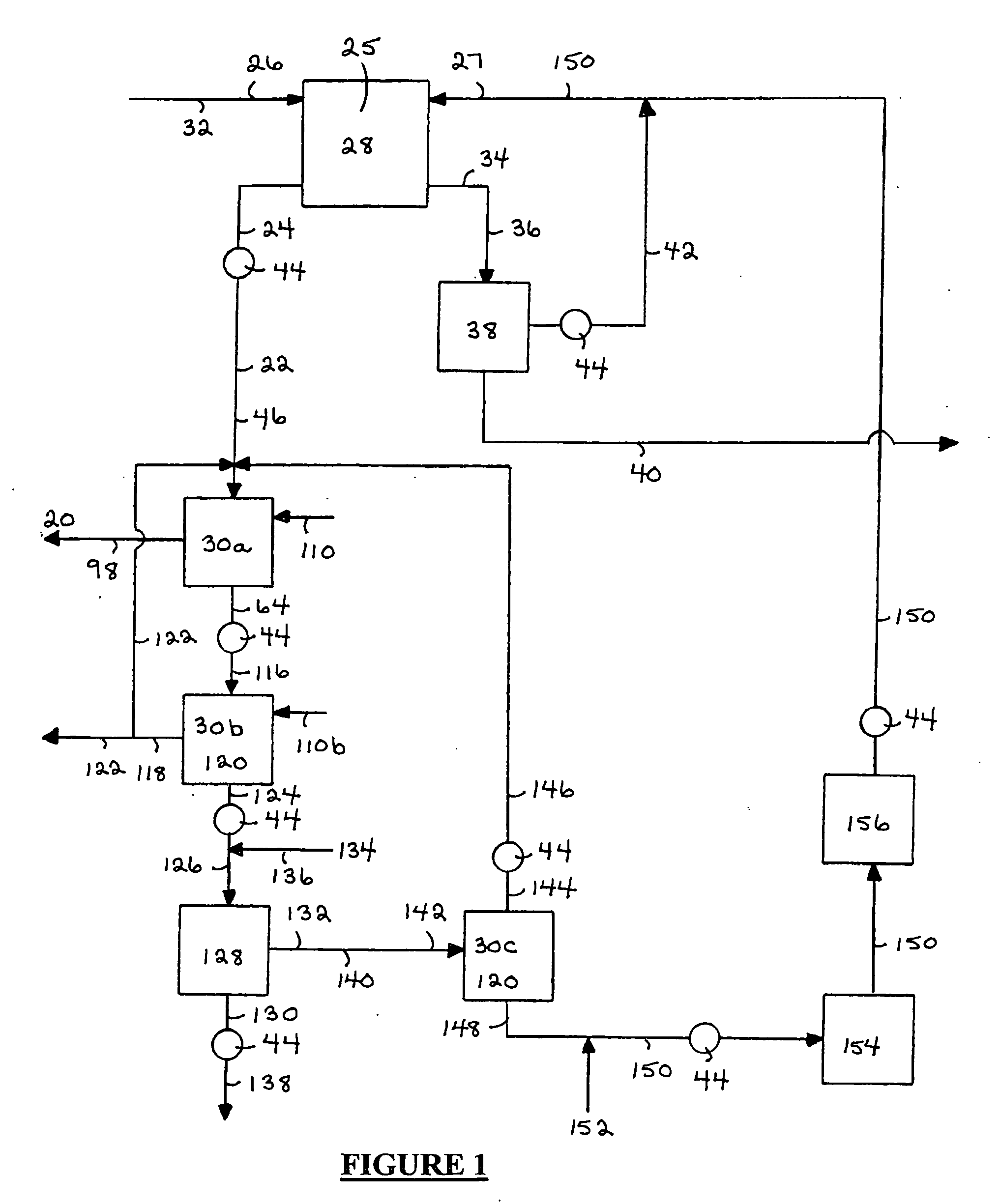
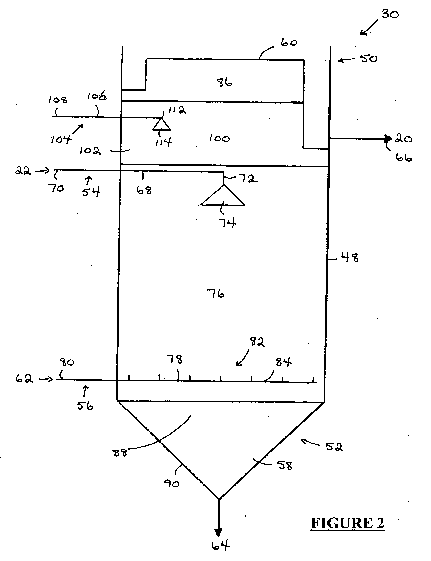
[0122] Referring to FIGS. 1-2, the present invention relates to a process for recovering a bitumen product (20) from a feed material (22) comprised of a bitumen froth (24) or a component derived from the bitumen froth (24). The bitumen froth (24) is produced from a slurry (25), comprised of oil sand (26) and water (27), by a primary separation process (28). Further, the process is comprised of the step of subjecting the feed material (22) to froth flotation in a column flotation cell (30).

[0123] In the preferred embodiment, the oil sand is comprised of a matrix of bitumen, solid particles and water. The bitumen is comprised of heavy oil or viscous hydrocarbons. The solid particles are comprised of mineral matter including coarse mineral matter, such as sand and rock, and fine mineral matter such as silt and clay.

[0124] The bitumen froth (24) is produced from a slurry (25) including the particles of oil sand (26) suspended within the water (27). The slurry (25) may be formed in any...


PUM

PropertyMeasurementUnit
temperatureaaaaaaaaaa
sizeaaaaaaaaaa

Abstract

A bitumen recovery process is provided which includes the step of providing a bitumen froth or a component derived from the bitumen froth as a feed material, wherein the bitumen froth is produced in a primary separation process from a slurry comprising oil sand and water. Further, the process includes the step of subjecting the feed material to froth flotation in a column flotation cell in order to recover a bitumen product from the feed material. Preferably, the froth flotation cell includes an underwash zone, wherein a bitumen-rich fraction of the feed material is passed through the underwash zone as the bitumen-rich fraction rises within the column flotation cell.

Description

FIELD OF INVENTION [0001] The present invention relates to a bitumen recovery process. Further, the present invention recovers a bitumen product from a feed material comprised of a bitumen froth produced in a primary separation process from a slurry comprising oil sand and water. BACKGROUND OF INVENTION [0002] Oil sand is essentially a matrix of bitumen, mineral matter and water. The bitumen component of oil sand consists of viscous hydrocarbons which behave much like a solid at normal in situ temperatures and which act as a binder for the other components of the oil sand matrix. The mineral matter component of oil sand typically consists largely of sand, but may also include rock, silt and clay. Sand and rock are considered to be coarse mineral matter, while clay and silt are considered to be fine mineral matter, where fines are defined as mineral matter having a particular size of less than 44 microns. The water component of oil sand consists essentially of a film of connate water...

Claims


Application Information

Patent Timeline
Patent Type & Authority Applications(United States)
IPC IPC(8): C10G1/04
CPCB01D21/0027B01D21/02B03B9/02B03D1/06B03D1/10B03D3/06C10G1/045C10G1/047B03D1/1468B03D1/245B03D1/082B03D1/1456
Inventor STRAND, WILLIAM L.
Owner BITMIN RESOURCES
Why Eureka
Try Eureka