Brake Control System

a technology of brake control and control system, applied in the direction of braking system, vehicle position/course/altitude control, instruments, etc., can solve the problems of vehicle acceleration above the target speed, loss of stability, and aggressive and intrusive deceleration

Active Publication Date: 2007-04-26
JAGUAR LAND ROVER LTD
View PDF9 Cites 34 Cited by
  • Summary
  • Abstract
  • Description
  • Claims
  • Application Information

AI Technical Summary

Benefits of technology

[0008] The system may further comprise a driver interface which can activate a hill descent mode in which a predetermined vehicle speed is set by automatically applying each brakes through the brake actuation means, in which the brake control means control the release of the braking effort when the vehicle is detected stationary on a slope under operation of the brake command input only during activation of the hill descent mode.

Problems solved by technology

On a steep slope, the rate of acceleration can be quite high requiring a large braking effort to prevent the speed of the vehicle from continuing past the target value, resulting in an aggressive and intrusive deceleration.
If the vehicle is in wet or muddy conditions, i.e. where the traction is poor, this aggressive intervention can cause the electronic control to perform an anti-lock braking function which will over-ride the hill descent control function to prevent the wheels from locking.
Hence the vehicle may accelerate above the target speed and lose stability.
The same problem can occur with a vehicle without hill descent mode, but with an anti-locking device, when the driver wants to reduce the speed of the vehicle after moving off from a standstill position on a downhill slope.

Method used


Image

  • Brake Control System
  • Brake Control System
  • Brake Control System

Examples


Embodiment Construction

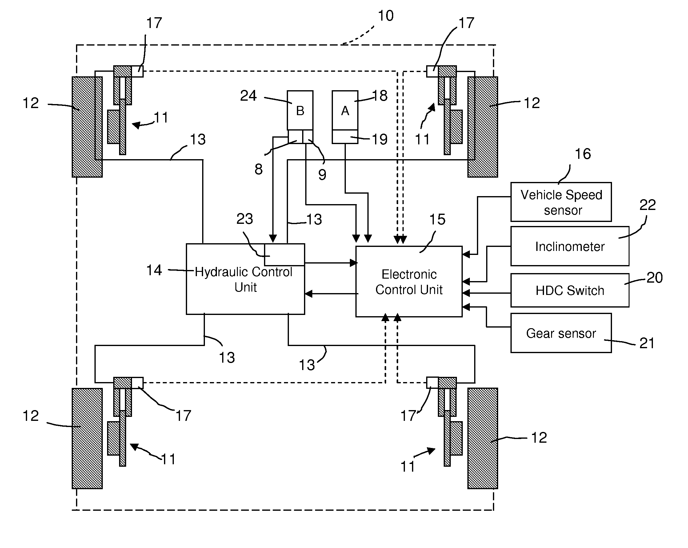
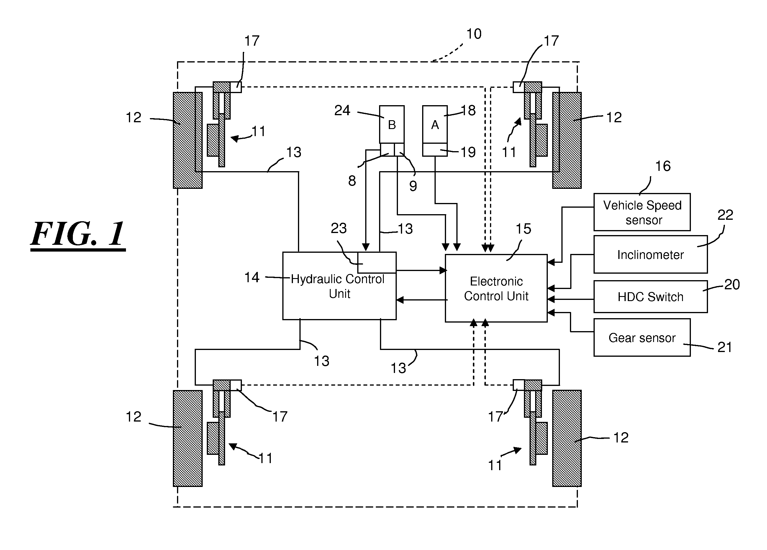
[0018] Referring to FIG. 1, there is shown a motor vehicle 10 in a dashed outline with a brake control system having a hill descent mode.

[0019] The brake control system includes in a conventional manner a braking arrangement with a disc brake 11 on each of four wheels 12. Each disc brake 11 is hydraulically operated through a hydraulic line 13 by a brake hydraulic control (HC) unit 14. The HC unit 14 is controlled by an electronic control (EC) unit 15. FIG. 1 is only a diagram of the most important functional components of the brake control system in accordance with the invention. Further details of the brake control system are described in EP 0 784 551 B1 and are included in the description by reference and thus will not be further described.

[0020] The EC unit 15 receives a vehicle speed signal from a vehicle speed sensor 16, an individual wheel speed signal from a wheel speed sensor 17 on each wheel 12 and a driver demand signal from an accelerator pedal 18 which incorporates an...


PUM


Abstract

A motor vehicle has an inclinometer to determine the steepness of the slope upon which the vehicle stands, brakes and a driver brake pedal for generating a braking effort in the brakes. The brakes are also controlled by a brake hydraulic control unit and an electronic control unit. The brake hydraulic control unit is arranged to control the release of the braking effort generated to stop the vehicle on a slope by the brake pedal at a release rate which varies as a function of the steepness of the slope determined by the inclinometer following operation of the brake pedal to release the brakes. The vehicle thus achieves controlled descent of a hill after a stationary position. Such a brake control system is particularly advantageous to a motor vehicle having a hill descent mode.

Description

TECHNICAL FIELD [0001] The present invention relates to a brake control system for a motor vehicle particularly but not exclusively comprising a hill descent mode which can be activated or de-activated by a driver interface in order to achieve controlled descent of a hill without the need for the driver to press a brake pedal. BACKGROUND [0002] The patent EP 0 784 551 B1 discloses a brake control system in particular for vehicles used in off-road conditions. The brake control system comprises an electronic control unit and a brake control system to control brakes associated with each wheel of the vehicle. A driver interface in the form of a switch is used to cause the control unit to enter a hill descent mode when the vehicle is also detected to be in gear. In this mode, the control unit controls the speed of the vehicle by braking to slow the vehicle when a detected vehicle speed is above a preset target speed. [0003] When driving off road with the hill descent mode active, it migh...

Claims


Application Information

Patent Timeline
Patent Type & Authority Applications(United States)
IPC IPC(8): B60T8/32B60T7/12B60T8/00B60T8/24
CPCB60T7/122B60T8/00B60T8/245B60T2201/04B60T2201/06B60T8/24B60T8/32B60T8/58
Inventor MASKELL, ANDREWOWEN, SIMONRICHARDS, KARL
Owner JAGUAR LAND ROVER LTD
Why Eureka
Try Eureka