Radar level gauge system and transmission line probe for use in such a system

a technology of transmission line and level gauge, which is applied in the direction of using reradiation, measuring devices, radio wave reradiation/reflection, etc., can solve the problems of insufficient accuracy, insufficient interface echo, and inability to use coaxial lines in very clean liquids, so as to improve accuracy, accurately measure several levels, and improve accuracy

Inactive Publication Date: 2007-04-26
ROSEMOUNT TANK RADAR
View PDF43 Cites 48 Cited by
  • Summary
  • Abstract
  • Description
  • Claims
  • Application Information

AI Technical Summary

Benefits of technology

[0010] In particular, the present invention is useful for determining reflections from several levels simultaneously. In such a case, the system is preferably arranged to receive reflections from at least two material interfaces inside said tank. An advantage with this is that it becomes possible to accurately measure several levels, when e.g. the tank is filled with a multilayered substance, and thus to measure even the level of a second content closest to the bottom of the tank. In one case, where the content to be gauged consists of oil, and the content closes to the bottom consists of water, it would be possible with a system according to this embodiment to compensate for the bottom content (water) and hence provide an even more accurate measurement of the “real” content to be gauged (oil). In another embodiment, it is provided a radar level gauge system wherein said dielectric enclosing structure comprises an outer surface forming an outer surface of said transmission line probe, and an inner surface arranged at a distance from said at least one probe line. Preferably, the distance (D) from an outer surface of said dielectrically enclosed transmission line probe to an outer surface of said at least one probe line is greater than half the radius (R) of said at least one probe line, more preferably greater than the radius (R) of said at least one probe line, and even more preferably greater than two times the radius (R) of said at least one probe line. By radius is in this context to be understood not only an ordinary radius for a probe line with a circular cross-section, but also the smallest distance between a center point and the outer boundary in case of other, non-circular cross-sections With the above-discussed thicknesses, the above-discussed dielectric enclosing structure provides for a very effecLive reduction of the microwave energy attenuating effect caused by the content to be gauged. As understood by the person skilled in the art, this embodiment of the present invention also provides for an even lower corrosive impact caused by the content in the tank. A possible implementation of this embodiment is by placing the at least one probe line inside for example a plastic tube In this case, both the pipe and the volume between the pipe and the at least one probe line will be part of the dielectric enclosing structure, and provide for a smaller microwave energy attenuating effect caused.by the content to be gauged.
[0011] The volume between the pipe and the at least one probe line may be filled with a gas, such as ambient air. However, in a preferred embodiment, the volume between said inner surface of said dielectrically enclosing structure and said at least one probe line is at least partly filled with a solid dielectric filling material. A thick plastic enclosure is one straightforward possibility, but alternatively, the solid dielectric filling material could be selected from crystalline and amorphous materials, such as a ceramic or glass. This embodiment will have a lower propagation velocity, and have the advantage of an even smaller microwave energy attenuating effect caused by the content to be gauged.
[0018] According to a further aspect of the present invention there is provided a transmission line probe, for use in a radar level gauge system arranged to measure a filling level of a content contained in a tank, wherein said transmission line probe comprises at least one probe line configured to guide transmitted microwave energy towards and from said content, and a dielectric structure essentially enclosing said at least one probe line, wherein said enclosing structure is arranged to reduce the microwave energy attenuating effect caused by said content to be gauged. As described above in relation to the first aspect of the present invention, this novel transmission line probe provides a plurality of advantages such as for example improved accuracy when measuring a filling level of a content contained in a tank, as the attenuation introduced by the content is reduced by the dielectric enclosing structure. Furthermore, the transmission line probe according to the present invention makes it possible to in an more accurate manner measure the level of the content closest to the bottom of the tank.

Problems solved by technology

Practical constraints determine when different types of transmission lines are used and for instance a coaxial line can only be used in very clean liquids, as there is no control over accumulation of deposit inside the tube.
However, there are problem with this and other similar systems disclosed in the prior art that uses parallel probe lines as they tend to provide insufficient accuracy of measurement, e.g. when measuring two interface levels between three materials (e.g. air / oil / water).
A typical problem in such cases is e.g. that the upper liquid introduces an attenuation, which makes the interface echo too weak when the radar has to pass through a thick layer of the upper liquid.
Furthermore, prior art systems using transmission line probes tends to have problems with corrosion due to the content contained in the tank.

Method used


Image

  • Radar level gauge system and transmission line probe for use in such a system
  • Radar level gauge system and transmission line probe for use in such a system
  • Radar level gauge system and transmission line probe for use in such a system

Examples


Embodiment Construction

[0026] In the present description, like reference numerals identify corresponding or similar structures and components.

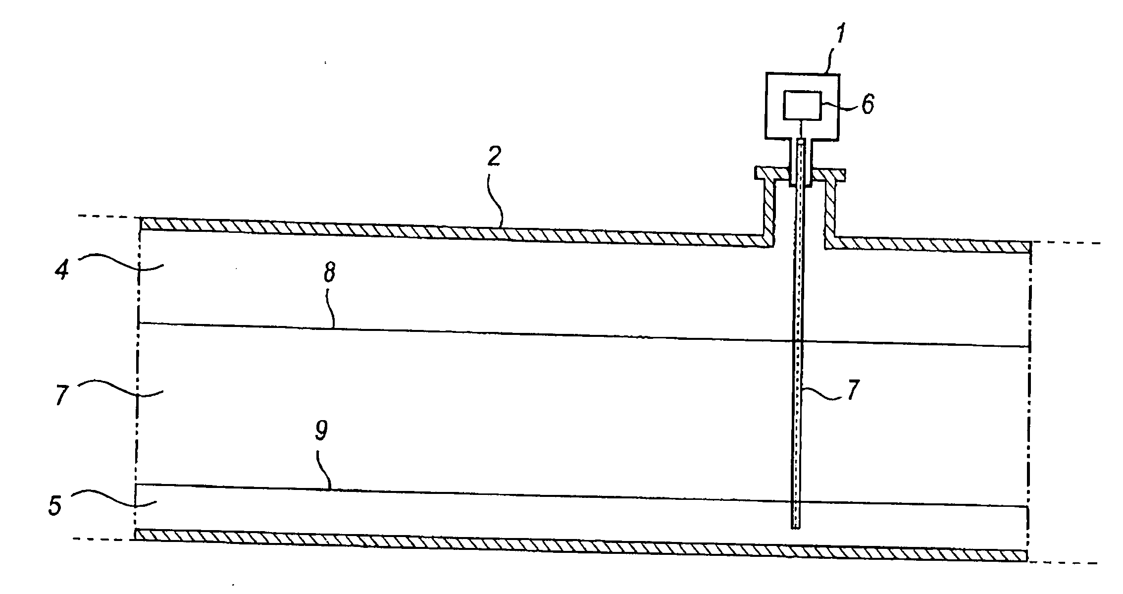
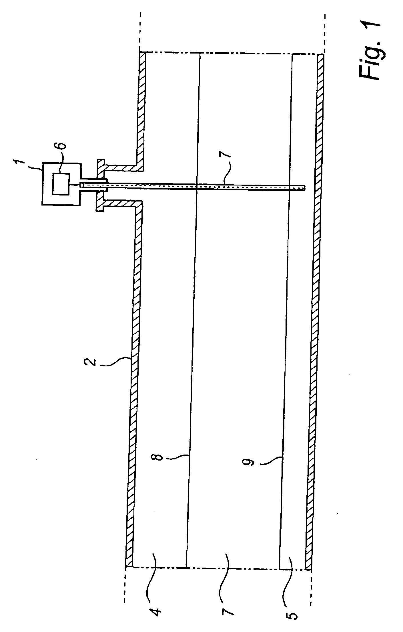
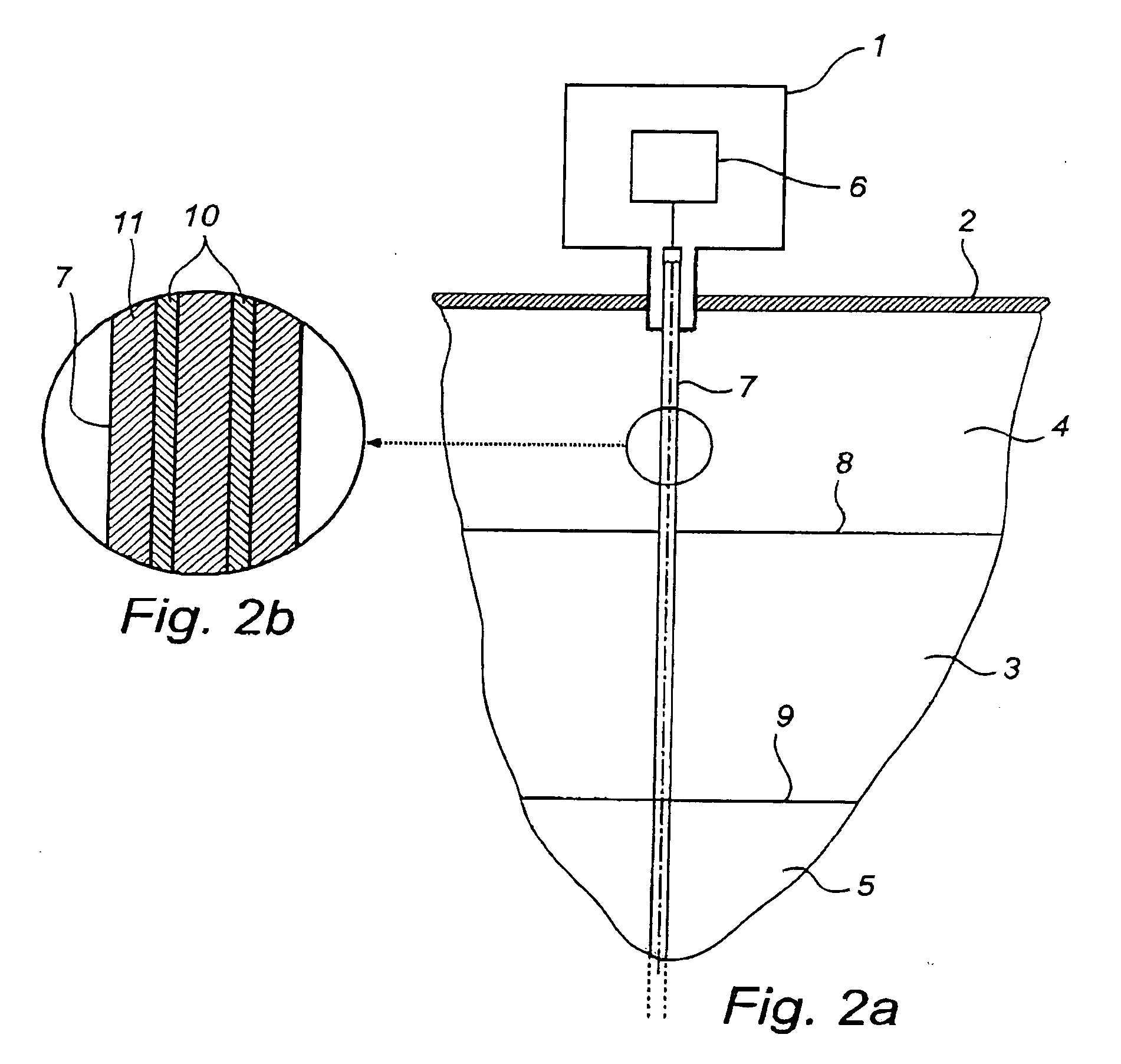
[0027] In FIG. 1, an example of a radar level gauge system according to the present invention is shown. Here, a radar level gauge system 1 has been installed onto a tank 2. Inside of the tank 2, content 3 has been deposited, such as oil. When the tank 2 is not completely full, the top part of the tank will comprise a layer of gas, and typically air 4. A small amount of water is often present in a tank (due to condensation), and this layer of water 5 can be seen on the bottom of tank 2. However, it is to be appreciated by the skilled addressee that the present radar level gauge system may be used for many other types of tanks and containers, and for many other types of filling materials.

[0028] The radar level gauge system 1 further comprises a transmitter and a receiver, and preferably a transceiver 6 consisting of a combined transmitter and receiver, arranged to t...


PUM


Abstract

A radar level gauge system, for measuring a filling level of a content contained in a tank, said radar level gauge system comprising a transmitter arranged outside said tank and configured to transmit microwave energy, a receiver arranged outside said tank and configured to receive reflected microwave energy, and a transmission line probe, comprising at least one probe line, configured to guide transmitted microwave energy towards and from said content, said probe at least partly disposed inside said tank, wherein said transmission line probe further comprises a dielectric enclosing structure enclosing at least a substantial part of said at least one probe line, wherein said dielectric enclosing structure is arranged to reduce the microwave energy attenuating effect caused by said content to be gauged. An advantage with the above system is its improved accuracy when measuring a filling level of a content contained in a tank, as the attenuation introduced by the content is reduced by the dicloctric enclosing structure.

Description

TECHNICAL FIELD OF THE INVENTION [0001] The present invention relates to a radar level gauge system for measuring a filling level of a content contained in a tank. The invention further relates to a transmission line probe for use in such a system. BACKGROUND OF THE INVENTION [0002] The process control and the transport industry employs process parameter gauges to monitor process parameters associated with substances such as solids, liquids and gasses in industries directed to chemicals, petroleum, pharmaceuticals, food, etc. Process parameters include pressure, temperature, flow, level, chemical composition and other properties. For measuring level of material contained in tanks, radar level gauge systems are often used. These systems normally employ a transmitter to transmit microwave energy, a receiver to receive a reflected fraction of said transmitted microwave energy, and a controller to evaluate the distance from the radar echo. In many cases a narrow beam antenna directed to...

Claims


Application Information

Patent Timeline
Patent Type & Authority Applications(United States)
IPC IPC(8): G01S13/08
CPCG01F23/284G01F23/00G01S13/88
Inventor EDVARDSSON, OLOV
Owner ROSEMOUNT TANK RADAR
Why Eureka
Try Eureka