Reflect array antennas having monolithic sub-arrays with improved DC bias current paths

a technology of reflect array antennas and monolithic sub-arrays, applied in the direction of resonant antennas, particular array feeding systems, space fed arrays, etc., can solve the problem of difficult dc bias line routing to each chip

Active Publication Date: 2007-04-26
RAYTHEON CO
View PDF6 Cites 168 Cited by
  • Summary
  • Abstract
  • Description
  • Claims
  • Application Information

AI Technical Summary

Benefits of technology

[0006] In some embodiments, a millimeter wave deterring device is provided. The device includes an active reflect array antenna and a W-band RF source. The W-band RF source may generate a substantially spherical wavefront for incident on the active reflect array antenna. The active reflect array antenna may amplify the incident wavefront and generate a high-power wavefront. The high-power wavefront may produce a deterring effect on a human target.

Problems solved by technology

As these substrates are tiled closely together to form a larger array, the routing of the DC bias lines to each chip becomes increasingly difficult due to the substantial DC current requirements of a large array.
This is especially a problem when lower-voltage devices requiring higher current are used for amplification.

Method used


Image

  • Reflect array antennas having monolithic sub-arrays with improved DC bias current paths
  • Reflect array antennas having monolithic sub-arrays with improved DC bias current paths
  • Reflect array antennas having monolithic sub-arrays with improved DC bias current paths

Examples


Embodiment Construction

[0019] The following description and the drawings illustrate specific embodiments of the invention sufficiently to enable those skilled in the art to practice them. Other embodiments may incorporate structural, logical, electrical, process, and other changes. Examples merely typify possible variations. Individual components and functions are optional unless explicitly required, and the sequence of operations may vary. Portions and features of some embodiments may be included in or substituted for those of others. Embodiments of the invention set forth in the claims encompass all available equivalents of those claims. Embodiments of the invention may be referred to, individually or collectively, herein by the term “invention” merely for convenience and without intending to limit the scope of this application to any single invention or inventive concept if more than one is in fact disclosed.

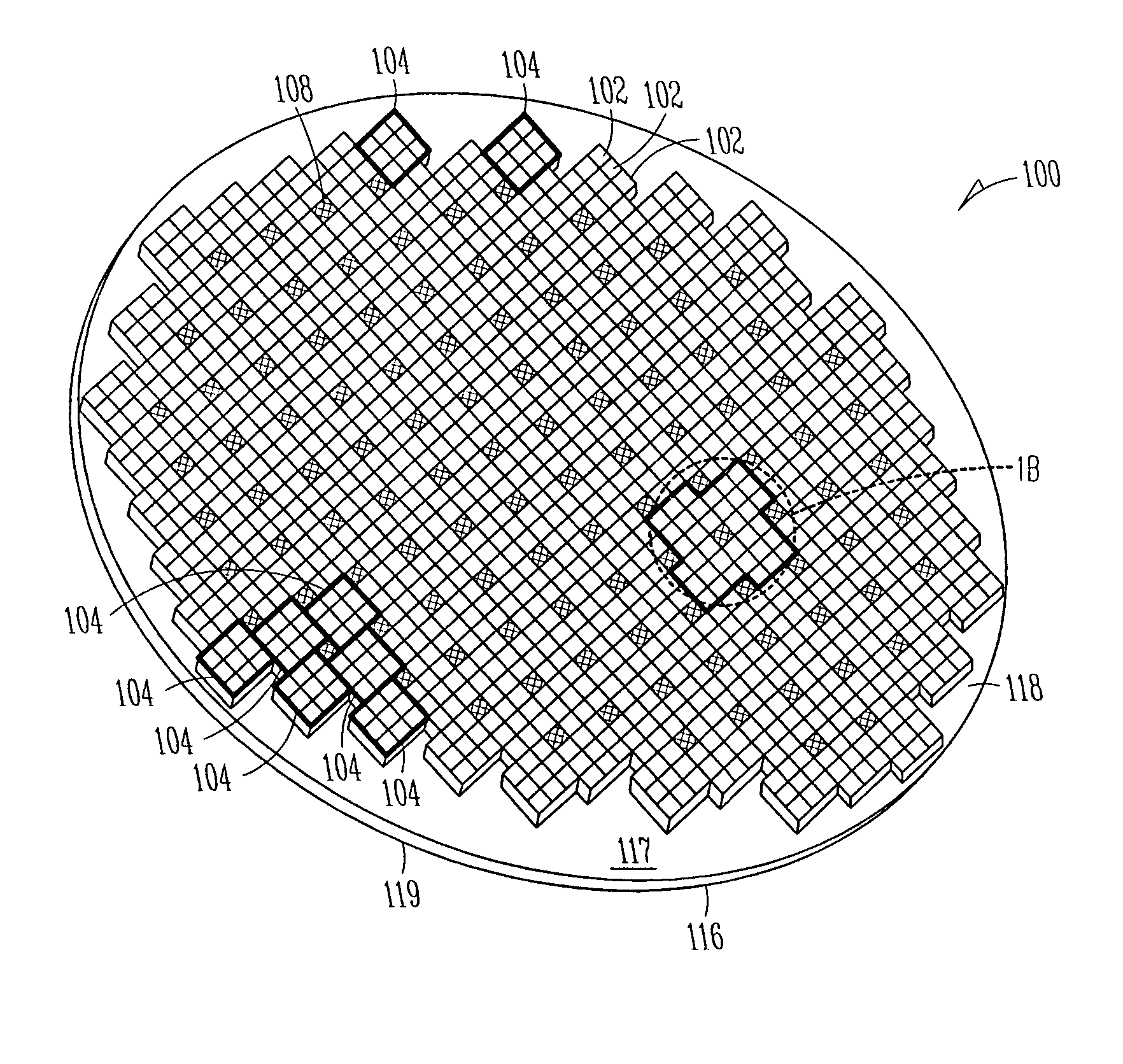
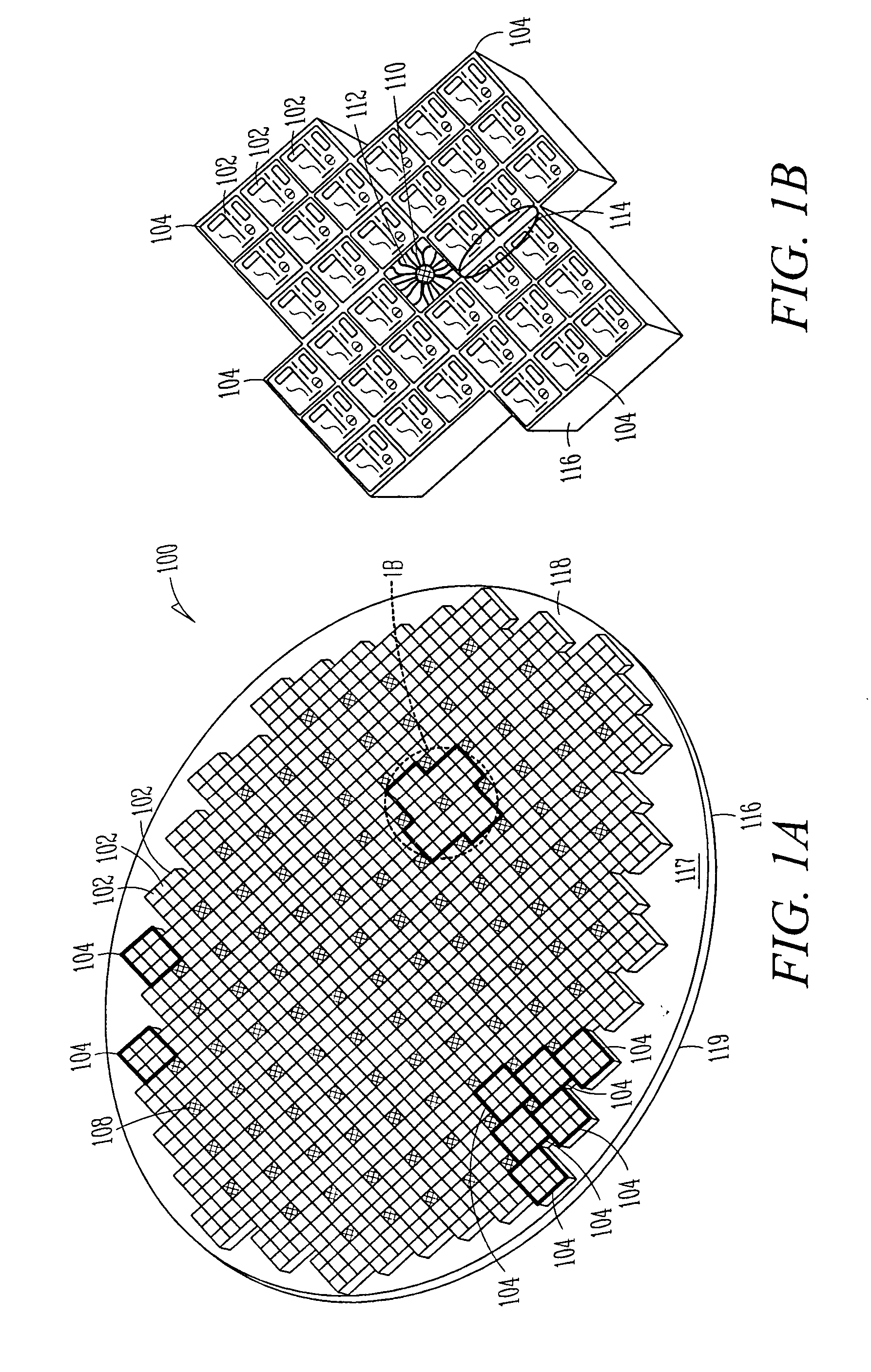
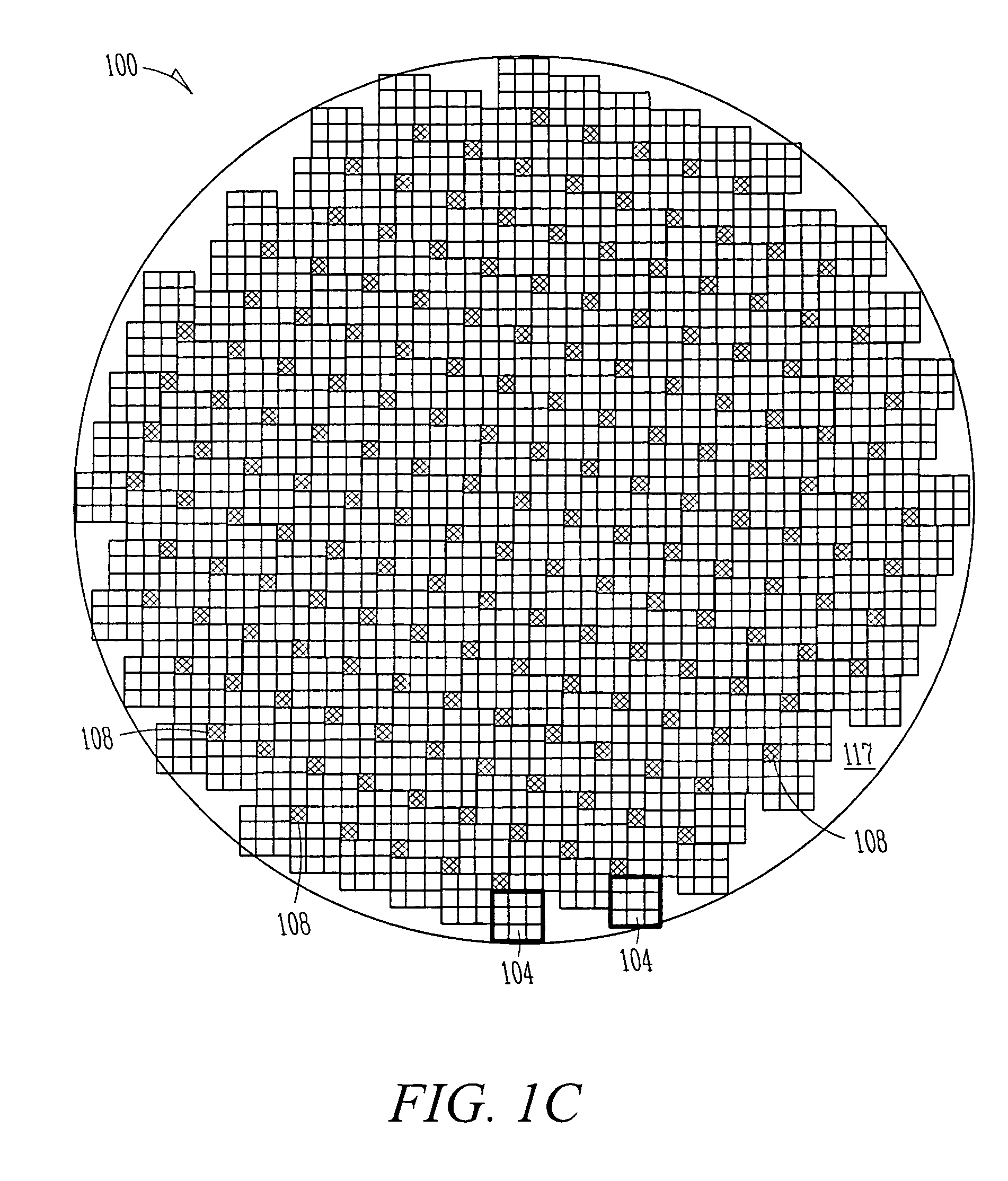
[0020] In active reflect array antennas, producing high power at millimeter wave frequencies, ...


PUM


Abstract

Embodiments of active array antennas are generally described herein. Other embodiments may be described and claimed. In some embodiments, a reflect array antenna includes an array of rectangular monolithic sub-array modules arranged in a non-uniform pattern to leave a plurality of rectangular gaps in the pattern. A DC feed pin located within each gap may provide DC bias current to the sub-array modules. The sub-array modules may be mounted on a heat sink in the non-uniform pattern. The heat sink may have holes aligned with the gaps to allow passage of the DC feed pins. In some embodiments, an array cooling assembly may be coupled to the back of the heat sink to cool the reflect array antenna with a coolant.

Description

TECHNICAL FIELD [0001] Embodiments of the present invention pertain to active reflective array antennas. BACKGROUND [0002] Active reflect array antennas that are fabricated with one or more monolithic substrates require substantial DC current for high-power applications. As these substrates are tiled closely together to form a larger array, the routing of the DC bias lines to each chip becomes increasingly difficult due to the substantial DC current requirements of a large array. This is especially a problem when lower-voltage devices requiring higher current are used for amplification. Thus, there are general needs for improved techniques for providing DC current in reflect-array antennas. SUMMARY OF THE INVENTION [0003] In some embodiments, a reflect array antenna includes an array of rectangular monolithic sub-array modules arranged in a non-uniform pattern to leave a plurality of rectangular gaps in the pattern. A DC feed pin located within each gap may provide DC bias current t...

Claims


Application Information

Patent Timeline
Patent Type & Authority Applications(United States)
IPC IPC(8): H01Q1/38
CPCH01Q3/46H01Q21/0018H01Q21/0093H01Q21/061
Inventor BROWN, KENNETH W.JONES, GEORGE K.BROWN, ANDREW K.DOLASH, WILLIAM E.
Owner RAYTHEON CO
Why Eureka
Try Eureka