Lens driving apparatus
a technology of driving apparatus and lens, which is applied in the direction of printers, cameras, instruments, etc., can solve the problems of difficult miniaturization of the lens driving apparatus, and achieve the effects of reducing the number of yokes, reducing the outer dimension, and enhancing the magnetic flux density of the magn
- Summary
- Abstract
- Description
- Claims
- Application Information
AI Technical Summary
Benefits of technology
Problems solved by technology
Method used
Image

Examples
second embodiment
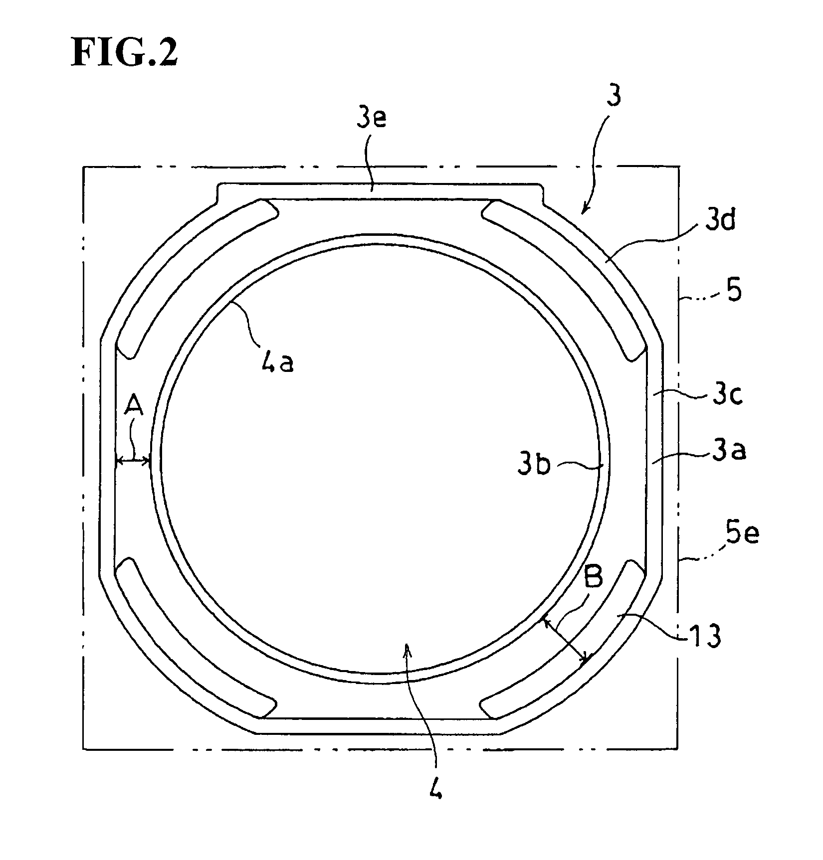
[0042]FIG. 6 is a perspective view illustrating a yoke extracted from a lens driving apparatus ; and FIG. 7 is a plane view of the yoke illustrated in FIG. 6.
[0043] As illustrated in FIGS. 6 and 7, the outer peripheral wall 3a of the yoke 3 is substantially square-shaped seeing from the plane, and the magnet 13, which is substantially triangularly shaped seeing from the plane, is provided on each corner portion of the outer peripheral wall 3a. An inner peripheral surface 13a of each magnet 13 is substantially arc-shaped, and the spaces between the inner peripheral walls 3b and the inner peripheral surfaces 13a of the respective magnets 13 are equally formed.
[0044] In this embodiment, each magnet 13, which is substantially triangularly shaped seeing from the plane, is fitted into the corner portion of the outer peripheral wall 3a of the yoke 3. Accordingly, in attaching the magnets 13 to the yoke 3, the magnets 13 can be positioned by only fitting the magnets 13 into the corner port...
third embodiment
[0047] In the third embodiment, each magnet 13, which is substantially triangularly shaped seeing from the plane, is fitted into the corner portion of the outer peripheral wall 3a, and an inner side wall 3g, which is arc-shaped seeing from the plane, is provided on an edge 4a of the opening portion 4 where each magnet 13 opposes. Moreover, in connection with each magnet 13, one side 13c of the triangle abutting to the outer peripheral wall 3a is longer than the other side 13d and end portions 13e of adjacent two magnets 13 are abutted to each other.
[0048] Since each magnet 13 may not be placed at the base side portion, a space (D shown in FIG.9) between the outer peripheral wall 3a and the edge 4a of the opening portion 4, which are positioned at the base side portion, can be made narrower than a space (C shown in FIG. 9) between the outer peripheral wall 3a and the inner side wall 3g, which are positioned at the base corner portion. As a result, the outer dimension of the base 5 ca...
first embodiment
[0051] In addition, the present invention is not limited to the aforementioned embodiments. It is needless to say that various embodiments and changes may be possible without departing from the gist of the present invention. In the aforementioned first embodiment, one magnet 13 is provided on the outer peripheral wall 3a of the yoke 3. However, the present invention is not limited to this, and multiple magnets 13 may be arranged thereon in the direction of the optical axis.
[0052] In the aforementioned second embodiment, the magnet 13, which is substantially triangularly shaped seeing from the plane, is provided at the corner portion of the yoke 3. However, the present invention is not limited to this. A support portion, which is substantially triangularly shaped seeing from the plane, is provided at the corner portion of the yoke 3, so that the magnet 13, which is substantially arc-shaped seeing from the plane, may be adhered to the support portion.
[0053] In the aforementioned firs...
PUM
 Abstract
Description
Claims
Application Information
 - R&D
- Intellectual Property
- Life Sciences
- Materials
- Tech Scout
- Unparalleled Data Quality
- Higher Quality Content
- 60% Fewer Hallucinations
Browse by: Latest US Patents, China's latest patents, Technical Efficacy Thesaurus, Application Domain, Technology Topic, Popular Technical Reports.
© 2025 PatSnap. All rights reserved.Legal|Privacy policy|Modern Slavery Act Transparency Statement|Sitemap|About US| Contact US: help@patsnap.com