

Control of storage system using disk drive device having self-check function
- Summary
- Abstract
- Description
- Claims
- Application Information
AI Technical Summary
Benefits of technology
Problems solved by technology
Method used
Image

Examples
first embodiment
A: First Embodiment
B: Second Embodiment
C: Third Embodiment
D: Fourth Embodiment
E: Fifth Embodiment
F: Sixth Embodiment
G: Seventh Embodiment
H: Eighth Embodiment
I: Ninth Embodiment
J: Variants
A: First Embodiment
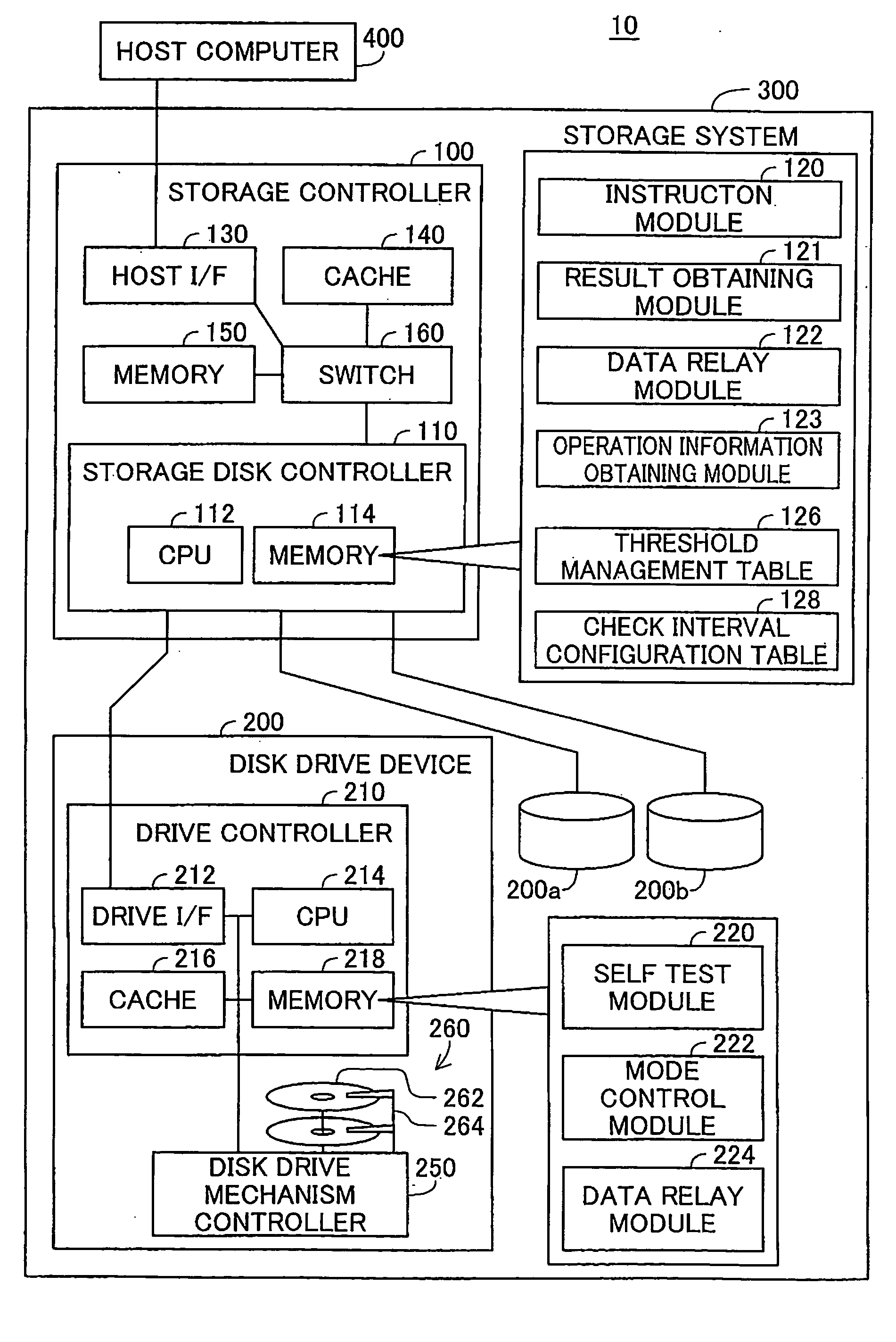
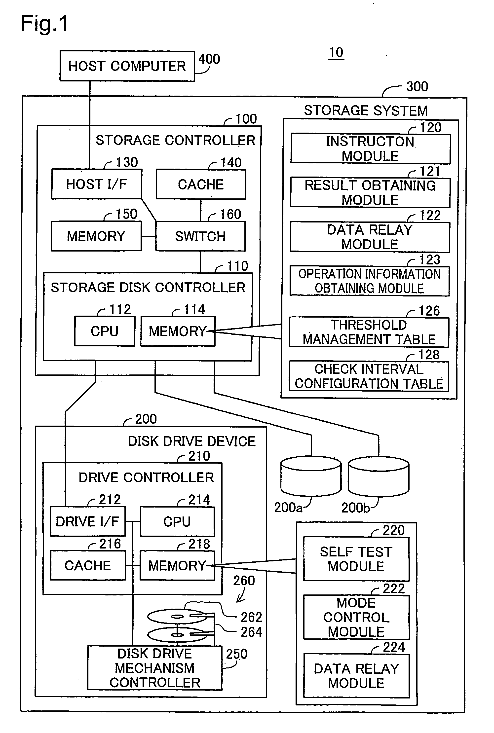
[0032]FIG. 1 is a schematic illustration of the structure of an embodiment of a data processing system according to the present invention. The data processing system 10 has a host computer 400 and storage system 300 that are connected to each other. The storage system 300 provides data storage areas to the host computer 400. The host computer 400 executes the desired functions while using the storage areas that have been provided. Functions of the host computer 400 include the file server functions for providing data files to client devices (not shown), and the database server functions for controlling various types of data.
[0033] The storage system 300 has a storage controller 100 and a plurality of disk drive devices 200, 200a, and 200b connected to the stora...
second embodiment
B: Second Embodiment
[0085]FIG. 6 is a flow chart of a procedure for a timing control process in the second embodiment. The difference from the first embodiment in FIG. 3 is that the instruction module 120 executes a timing control process according to an up timing mode instead of the down timing mode. In the up timing mode, a self test is run responsive to switching the operating mode of the disk drive device 200 from a non-active mode to the active mode. The structure of the data processing system is the same as that of the data processing system in FIG. 1.
[0086] In the initial step S200, the data relay module 122 (FIG. 1) transmits an instruction to change the operating mode from a non-active mode to the active mode (mode select request) to the drive controller 210. In the second embodiment, the data relay module 122 transmits a command to the drive controller 210 to switch the operating mode from a non-active mode to the active mode when the storage disk controller 110 receives ...
third embodiment
C: Third Embodiment
[0093]FIG. 7 is a flow chart of a procedure for selecting the timing mode in a third embodiment. The difference from the first and the second embodiments is that the instruction module 120 has two modes, a constant interval mode and an access timing mode, as timing modes. The structure of the data processing system is the same as that of the data processing system in FIG. 1.
[0094] In the constant interval mode, the instruction module 120 has the drive controller 210 run a self test at constant intervals. In the access timing mode, the instruction module 120 determines whether to run the self test according to the state of access to the disk drive device. Between these two timing modes, the self test is run at timing (check timing) that is different from each other. Details on the modes are given below. It is assumed that the disk drive device 200 is the target in the following description. The details of the process are the same when targeting the other disk driv...
PUM
 Abstract
Description
Claims
Application Information