Method of transferring signals between a memory device and a memory controller

Active Publication Date: 2007-04-26
POLARIS INNOVATIONS
View PDF8 Cites 6 Cited by
  • Summary
  • Abstract
  • Description
  • Claims
  • Application Information

AI Technical Summary

Benefits of technology

[0015] According to one aspect of the present invention the reliability of transfer of signals between a memory controller and a memory device is increased without impairing the performance. In som

Problems solved by technology

A number of fundamental problems now call for a completely new design or architecture of memory devices, memory controllers and t

Method used


Image

  • Method of transferring signals between a memory device and a memory controller
  • Method of transferring signals between a memory device and a memory controller
  • Method of transferring signals between a memory device and a memory controller

Examples


Example

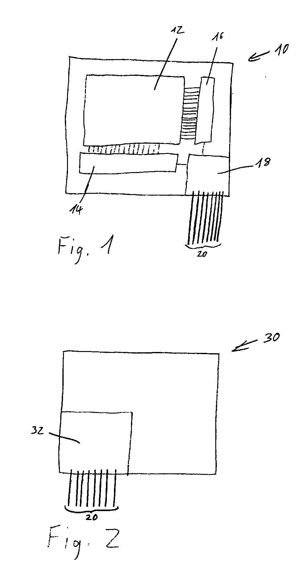
[0025]FIG. 1 is a schematic representation of a memory device 10 according to the present invention. The memory device 10 comprises an array 12 of memory cells, a column address decoder 14 and a row address decoder 16. The column and row address decoders 14, 16 are connected to an input / output section 18 for transmitting and receiving command address and data signals via lines 20. The input / output section 18 is involved in the communication between the memory device 10 and a memory controller (described below with respect to FIG. 2). FIG. 1 is a simplified representation of the memory device 10. Merely some of its elements and functional blocks are displayed.

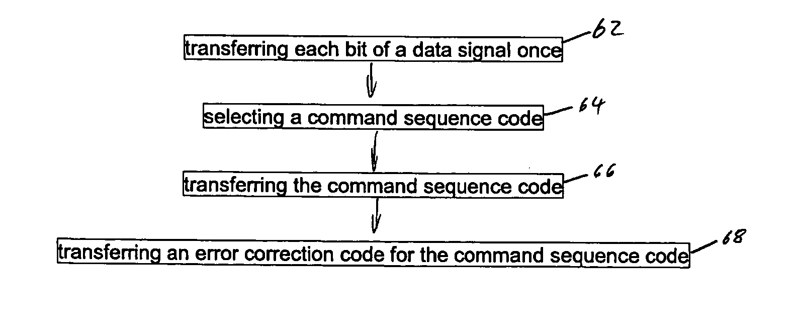
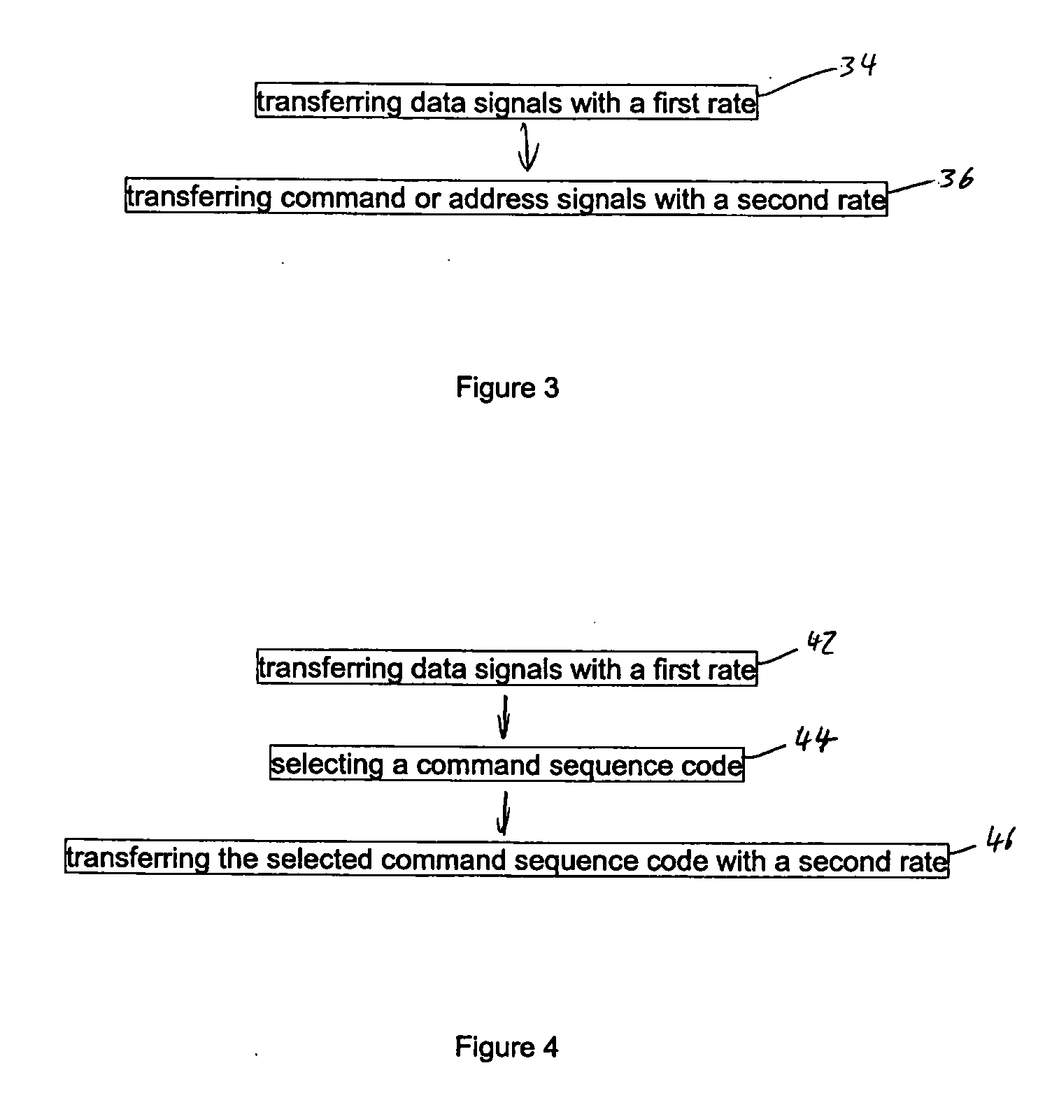
[0026] The input / output section 18 is designed for receiving and transmitting data signals with a first rate and command and / or address signals with a second rate lower than the first rate. Additionally or alternatively the input / output section 18 is designed for receiving and / or transmitting command sequence codes identifying ...


PUM


Abstract

Method and apparatus for communication (e.g., transmitting and/or receiving) command, address and data signals from a memory device to a memory controller or vice versa. The data signals are transferred with a first rate and command signals and/or address signals are transferred with a second rate lower than a first rate. Additionally or alternatively a command sequence code identifying a command sequence from a predefined group of command sequences is transferred with the first or with the second rate.

Description

BACKGROUND OF THE INVENTION [0001] 1. Field of the Invention [0002] The present invention refers to a method of transferring command, address and data signals from a memory device to a memory controller or vice versa. Particularly, the present invention provides a more reliable transfer of command and address signals with a lower risk of bit errors. [0003] 2. Description of the Related Art [0004] Conventionally, command, address and data signals are transferred between memory devices and a memory controller by a number of parallel lines. In response to growing computing capacities and growing amounts of information to be stored, the clock frequency and the data rate of this transfer are increased continuously. A number of fundamental problems now call for a completely new design or architecture of memory devices, memory controllers and their communication. [0005] According to new concepts and technologies, command, address and data signals will be transferred in frames, each frame c...

Claims


Application Information

Patent Timeline
IPC IPC(8): G11C8/00
CPCG11C8/18G11C8/04
Inventor WALLNER, PAULSCHAEFER, ANDREHEIN, THOMASGREGORIUS, PETER
Owner POLARIS INNOVATIONS
Why Eureka
Try Eureka