
Digital broadcasting receiving system and method

a digital broadcasting and receiving system technology, applied in the field of digital broadcasting receiving system and transmission stream receiving, can solve the problems of poor reception sensitivity in poor channels, almost no effect on improving the inferior reception performance, and improvement of a normal stream hardly contributes to improving the reception sensitivity. , to achieve the effect of improving the reception sensitivity and removing nois

Inactive Publication Date: 2007-04-26
SAMSUNG ELECTRONICS CO LTD
View PDF16 Cites 111 Cited by
  • Summary
  • Abstract
  • Description
  • Claims
  • Application Information

AI Technical Summary

Benefits of technology

[0017] Accordingly, the present general inventive concept has been made to solve the above-mentioned and / or other problems, and an aspect of the present general inventive concept provides a digital broadcasting receiving system and method for receiving a dual transmission stream including a normal stream and a robustly processed turbo stream to restore the turbo stream and the normal stream and eraser decoding the restored turbo stream to remove noise, so as to improve reception sensitivity of an Advanced Television Systems Committee Vestigial Sideband (ATSC VSB) way, such as in the United States terrestrial digital television (DTV) system.

Problems solved by technology

Thus, reception sensitivity is poor in a poor channel, particularly, in a Doppler fading channel.
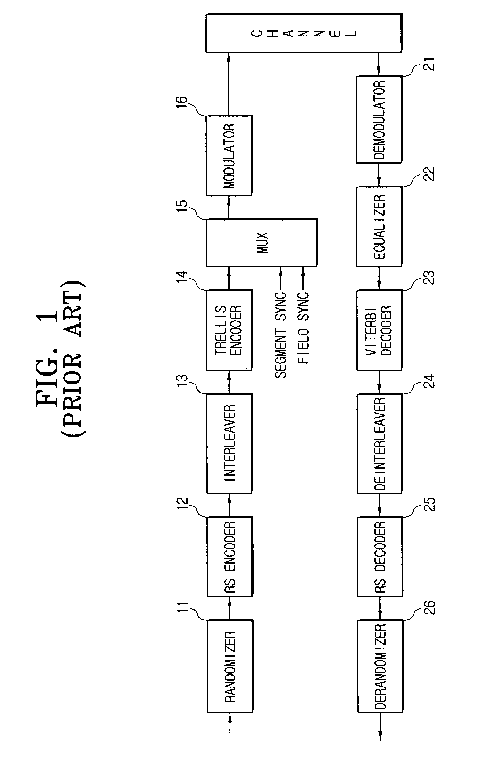
However, the United States terrestrial digital broadcasting system shown in FIG. 1 has almost no effect on improving the inferior reception performance in a multipath channel, due to the transmission of the existing normal data, although it transmits the dual stream produced by adding the robust data to the normal data.
In other words, the improvement of a normal stream hardly contributes to improving the reception sensitivity.
Also, a turbo stream cannot greatly contribute to improving reception sensitivity in a multi-path environment.

Method used


Image

  • Digital broadcasting receiving system and method
  • Digital broadcasting receiving system and method
  • Digital broadcasting receiving system and method

Examples


Embodiment Construction

[0037] Reference will now be made in detail to the present embodiments of the present invention, examples of which are illustrated in the accompanying drawings, wherein like reference numerals refer to the like elements throughout. The embodiments are described below in order to explain the present invention by referring to the figures.

[0038] In the following description, same drawing reference numerals are used for the same elements even in different drawings. The matters defined in the description such as a detailed construction and elements are nothing but the ones provided to assist in a comprehensive understanding of the invention. Thus, it is apparent that the aspects of the present invention can be carried out without those defined matters. Also, well-known functions or constructions are not described in detail since they would obscure the invention in unnecessary detail.

[0039]FIG. 3 is a block diagram illustrating a configuration of a digital broadcasting receiving system ...


PUM


Abstract

A digital broadcasting receiving system and method, where the digital broadcasting receiving system includes: a demodulator receiving and demodulating a dual transmission stream including a turbo stream and a normal stream; an equalizer equalizing the demodulated dual transmission stream; a first processor restoring normal stream data from the equalized dual transmission stream; and a second processor restoring turbo stream data from the equalized dual transmission stream and eraser decoding the turbo stream data. Thus, the reception sensitivity of a transmission stream including a turbo stream can be improved.

Description

CROSS-REFERENCE TO RELATED APPLICATIONS [0001] This application claims the benefit of Korean Application No. 2006-68064, filed Jul. 20, 2006, in the Korean Intellectual Property Office, and U.S. Provisional Application No. 60 / 728,777 filed Oct. 21, 2005, U.S. Provisional Application No. 60 / 734,295 filed Nov. 8, 2005, U.S. Provisional Application No. 60 / 738,050 filed Nov. 21, 2005, U.S. Provisional Application No. 60 / 739,448 filed Nov. 25, 2005, and U.S. Provisional Application No. 60 / 788,707 filed Apr. 4, 2006 filed in the United States Patent and Trademark Office, the disclosures of which are incorporated herein by reference. BACKGROUND OF THE INVENTION [0002] 1. Field of the Invention [0003] An aspect of the present invention relates to a digital broadcasting receiving system and method for receiving a transmission stream used for digital broadcasting, and more particularly, to a digital broadcasting receiving system and method for receiving and processing a dual transmission stre...

Claims


Application Information

Patent Timeline
IPC IPC(8): H04L27/06
CPCH03M13/253H04L25/03006H03M13/2936H03M13/2957H03M13/2966H03M13/2972H03M13/6538H04H20/33H04H40/18H04L1/005H04L1/0054H04L1/0065H04L1/0066H04L1/0067H04L1/007H04L1/0071H03M13/2933H04N7/015
Inventor YU, YUNG-PILJEONG, HAE-JOOPARK, EUI-JUNKIM, JOON-SOOKWON, YONG-SIKJEONG, JIN-HEECHANG, YONG-DEOKJI, KUM-RANKIM, JONG-HUN
Owner SAMSUNG ELECTRONICS CO LTD
Learn More