Belt rotation device for image forming device

a technology of rotating device and belt, which is applied in the direction of instruments, electrographic process equipment, optics, etc., can solve the problems of affecting the detection accuracy of the belt, the belt may peel off, etc., and achieves the effect of suppressing the effect of stable drive of the belt, accurate position detection over a long period of time, and simple configuration

Inactive Publication Date: 2007-04-26
KYOCERA DOCUMENT SOLUTIONS INC
View PDF6 Cites 10 Cited by
  • Summary
  • Abstract
  • Description
  • Claims
  • Application Information

AI Technical Summary

Benefits of technology

[0015] The belt rotation device for an image forming device relating to claim 4 is a belt rotation device according to any one of claims 1 through 3, wherein the thickness of the portion to be detected is preferably 200 μm or less. When the protruding member is attached on the belt inner periphery, if the portion to be detected is too thick, stable drive of the belt may be inhibited, and transfer displacement due to the thickness of the portion to be detected may occu

Problems solved by technology

When the tensile elastic modulus of the member constituting the portion to be detected is larger than the tensile elastic modulus of the endless belt, the member constituting the portion to be detected cannot match belt deformation on roller winding unit, that is, t

Method used


Image

  • Belt rotation device for image forming device
  • Belt rotation device for image forming device
  • Belt rotation device for image forming device

Examples


Embodiment Construction

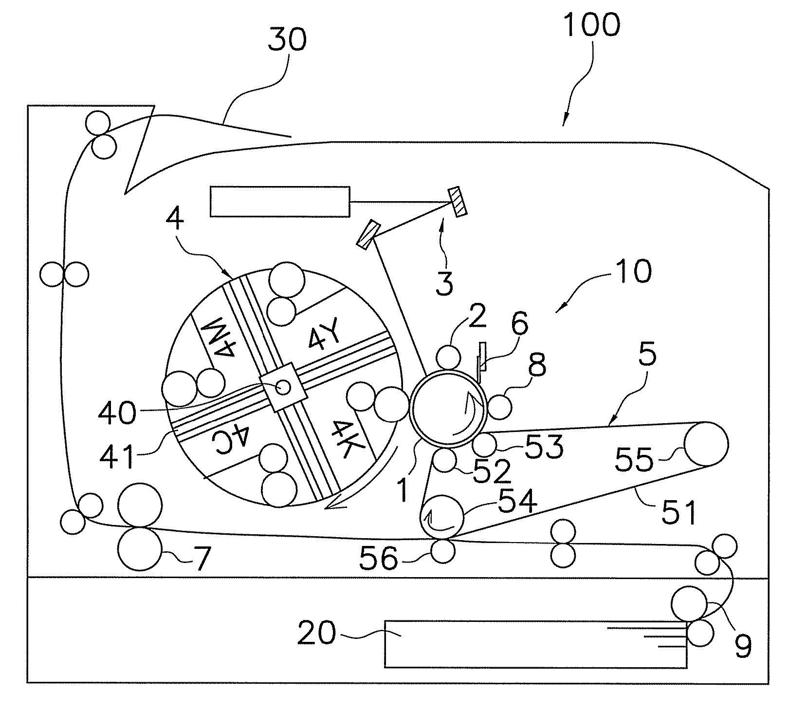
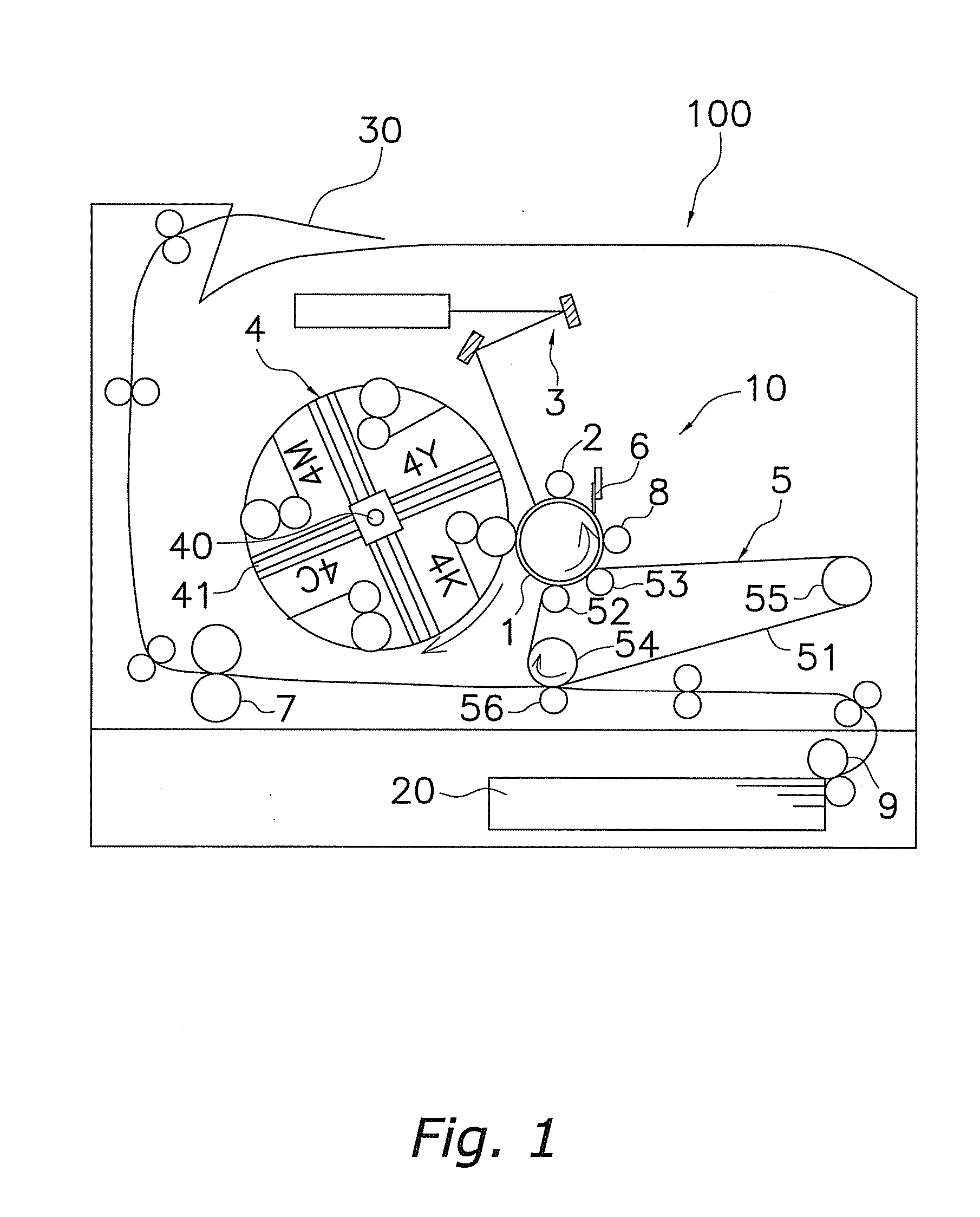
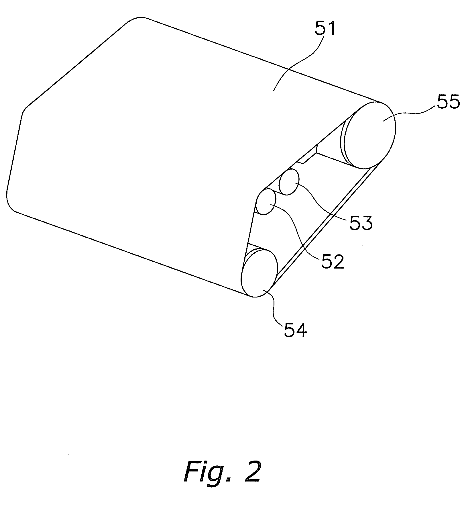
[0022]FIG. 1 shows an outline of the constitution of a color image forming device employing one embodiment of the present invention. A color image forming device 100 has an image forming unit 10 roughly in the center thereof The image forming unit 10 comprises a photosensitive drum 1, and, disposed around the photosensitive drum 1, a charging device 2, exposure device 3, development device 4, transfer device 5, cleaning device 6 and sliding roller 8. Further, a fuser device 7 is disposed downstream of the photosensitive drum 1 in the sheet transport direction. The image forming device has a feed unit 20 provided at a lower portion thereof, and a feed roller 9 disposed downstream of the feed unit 20 in the sheet feed direction.

[0023] An electrostatic latent image is formed on the surface of the photosensitive drum 1. For the present embodiment, an amorphous silicon photoconductor is used, comprising the following laminate structure laid down in the order given: a carrier injection p...


PUM


Abstract

As a portion to be detected of a belt 51, a protrusion 60 is provided on the width direction edge of the endless belt 51, and the tensile elastic modulus of the member forming the protrusion 60 is smaller than the tensile elastic modulus of the member forming the endless belt 51. Because the difference between the tensile elastic modulus of the protrusion material 60 and the tensile elastic modulus of the belt 51 is suitable, the protrusion material 60 can keep up with deformation of the belt 51 on the winding unit of the roller 54, so that a large stress does not arise in the surface direction on the adhesive interface between the belt 51 and protrusion material 60. Therefore, peeling of the protrusion material 60 by the driving of the belt 51 over a long period of time can be prevented.

Description

FIELD OF THE INVENTION [0001] The present invention relates to a belt rotation device for an image forming device, and more particularly to a belt rotation device having provided therein a portion to be detected for detecting a belt member position. BACKGROUND INFORMATION [0002] An electrophotographic image forming device has provided therein, in the vicinity of a photosensitive drum, charging means, exposure means, development means, transfer means, cleaning means, and other means. After the photosensitive drum is charged by charging means, exposure is performed by exposure means to form an electrostatic latent image on the photosensitive drum surface and this image is developed by development means. Thereafter, the developed toner image is transferred onto a transfer material by transfer means and fused by fuser means, and the transfer material on which an image has been formed is output to an output unit. Residual developer remaining on the photosensitive drum is cleaned by clean...

Claims


Application Information

Patent Timeline
IPC IPC(8): G03G15/01
CPCG03G15/0131G03G2215/0158G03G2215/0177
Inventor MIYAMOTO, HIDETOSHIUNO, KOUJI
Owner KYOCERA DOCUMENT SOLUTIONS INC
Why Eureka
Try Eureka