Control system

a control system and control system technology, applied in the field of control systems, can solve the problems of not providing for the status of the remote mounted antenna system, the signaling scheme of van amesfoort is relatively complex, and the cost and complexity of the cabling may therefore be very significan

Inactive Publication Date: 2007-04-26
KINCARD DWAYNE
View PDF9 Cites 42 Cited by
  • Summary
  • Abstract
  • Description
  • Claims
  • Application Information

AI Technical Summary

Benefits of technology

[0008] A system for sending uplink control signals to antennas and receiving downlink signals therefrom, where the uplink signals may be used to control antenna position and operate antenna switches and the like, and the downlink signals may indicate antenna position, the uplink signals being in the form of digital signals having two voltage levels within the range of a DC supply superimposed on the RF signals on the antenna feeder, and the downlink signals being digital signals in the form of changes in the DC current on the feeder, preferably generated by a load having two resistance values, as further discussed and as shown in the drawings

Problems solved by technology

However, typically, the antenna switch and the rotator each require separate power cables and control cables of their own.
The cost and complexity of cabling may therefore be very significant, even if a remote antenna switch is employed.
The signaling scheme of Van Amesfoort is relatively complex, as it uses both DC signals and an audio tone.
It also does not provide for any indication of the status of the remotely mounted antenna system, which includes only a single fixed antenna dish.

Method used


Image

  • Control system
  • Control system
  • Control system

Examples


Embodiment Construction

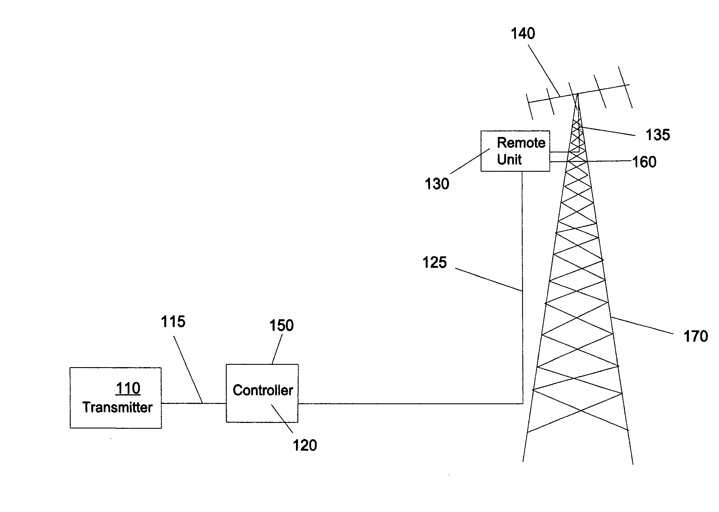
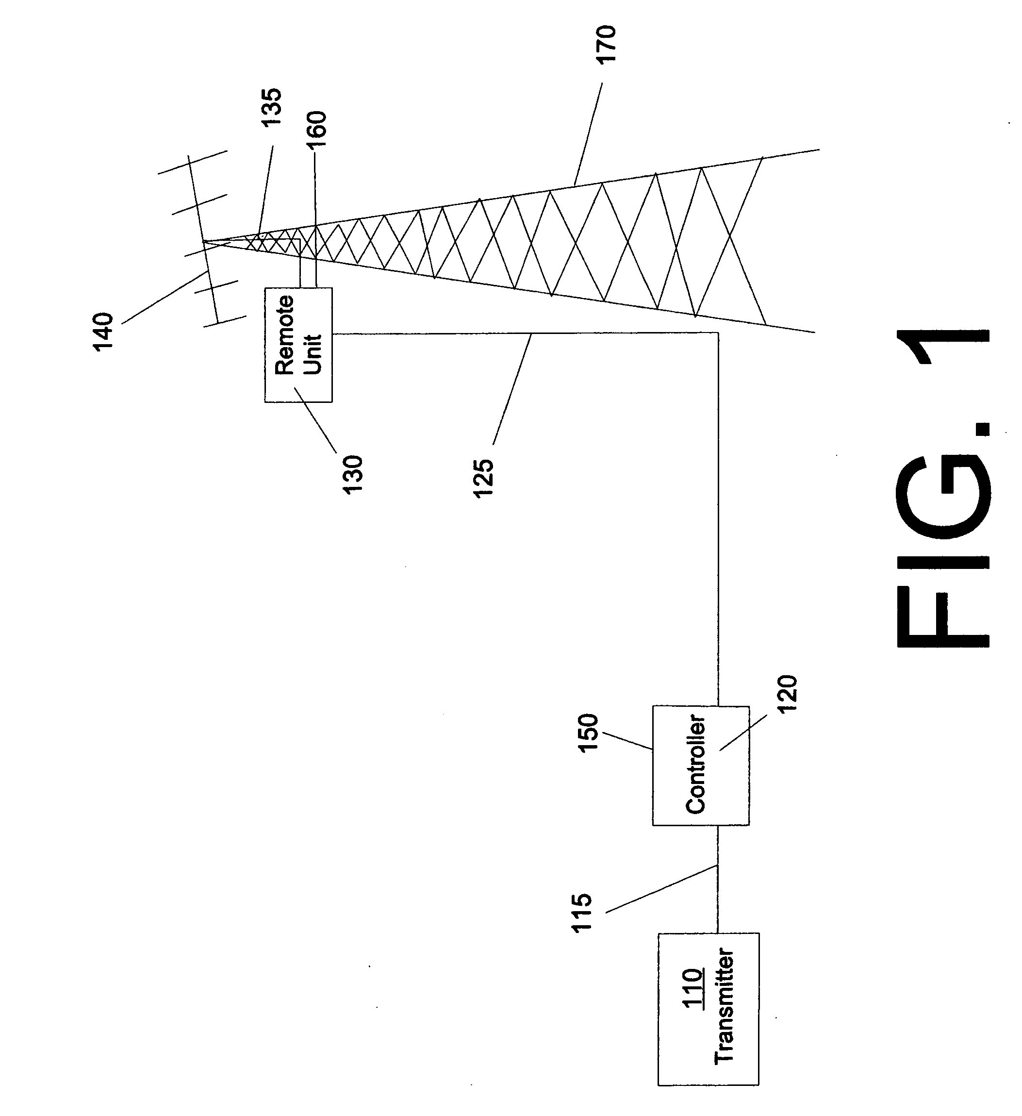
[0017]FIG. 1 is a view of a system according to a preferred embodiment of the invention. A transmitter 110 is connected via a short feed line 115 to a controller 120, which is in turn connected via feed line 125 to remote unit 130. Control inputs 150 are applied to control unit 120. A further short feed line connects remote unit 130 to an antenna 140 and provides control signals at output 160. Uplink signals from the controller 120 are recovered by the remote unit 130, and may for example be used to control rotation of antenna 140 and / or to control an antenna switch to select between a plurality of antennas. For satellite working, i.e. for OSCAR satellites (Orbiting Satellites Carrying Amateur Radio), separate rotators may be simultaneously controlled for azimuth and elevation.

[0018] Transmitter 110 may be a mere transmitter, or preferably a transceiver combining transmit and receive functions, or a receiver may be substituted therefor without departing from the scope of the invent...


PUM


Abstract

A system for sending uplink control signals to antennas and receiving downlink signals therefrom, where the uplink signals may be used to control antenna position and operate antenna switches and the like, and the downlink signals may indicate antenna position, the uplink signals being in the form of digital signals having two voltage levels within the range of a DC supply superimposed on the RF signals on the antenna feeder, and the downlink signals being digital signals in the form of changes in the DC current on the feeder, generated by a load having two resistance values.

Description

BACKGROUND OF THE INVENTION [0001] 1. Field of the Invention [0002] The invention relates to a system for sending uplink control signals to antennas and receiving downlink signals therefrom. More particularly, the invention relates to a system where the uplink signals may be used to control antenna position and operate antenna switches and the like, and the downlink signals may indicate antenna position. [0003] 2. Discussion of the Background [0004] It is relatively common, for example in amateur radio, to mount several antennas on a single mast or tower. Each of these antennas has to be connected via a length of high frequency feed line, such as a coaxial cable. Loss in these cables is proportional to length as well as to frequency. This can be mitigated by selecting low loss types of cables, but at significant cost. Directional antennas are often used to provide significant gain, but must then be rotatable to cover all directions. A remote antenna switch may be used to select the ...

Claims


Application Information

Patent Timeline
Patent Type & Authority Applications(United States)
IPC IPC(8): H04B7/185H04B1/06
CPCH01Q1/246
Inventor KINCARD, DWAYNE
Owner KINCARD DWAYNE
Why Eureka
Try Eureka