Rubber element for compression elastic coupling

a compression elastic and rubber element technology, applied in the direction of yielding couplings, rubber-like materials, springs/dampers, etc., can solve the problems of easy deformation of play between input shafts, uneven compression of elastic components, and likely loosening of connection between input shafts and output shafts, so as to prevent excessive expansion of rubber elements and excessive deformation of elastic members , the effect of reducing the length of continuous use of compression elastic couplings

Active Publication Date: 2007-04-26
KAWASAKI HEAVY IND LTD
View PDF11 Cites 4 Cited by
  • Summary
  • Abstract
  • Description
  • Claims
  • Application Information

AI Technical Summary

Benefits of technology

[0028] The rubber elements of the compression elastic coupling of the present invention have the following excellent effects.
[0029] 1) The protrusions can prevent the excessive expansion of the rubber element and the excessive deformation of the elastic member. Therefore, the compression elastic coupling can be formed in a small diameter, permanent strain produced in the elastic member by the long, continuous use of the compression elastic coupling can be reduced and the compression elastic coupling has high fatigue strength and a long life.
[0030] 2) The protrusions having the smoothly curved surfaces can avoid stress concentration and stress distribution and strain in the rubber element can be adjusted by changing the width and the height of the protrusions without changing the physical properties of the elastic member.
[0031] 3) The area of contact between the elastic member and the mounting plate can be increased by forming the circumferential step in the mounting plate, the part in contact with the elastic member is formed in a direction parallel to the directions in which the rubber element is tensioned and compressed to distribute load during variation. Thus stress concentration on parts of the mounting plate and the elastic member in contact with each other can be eased and damaging the surface of the elastic member can be suppressed even under severe conditions.
[0032] 4) A circumferential outer part of the rubber element included in the compression elastic coupling is caused to bulge out by high compression and a part of the elastic member in contact with the mounting plate and a central part of the elastic member are likely to be differently deformed. In the rubber element of the present invention, the protrusions make the elastic member bulged smoothly and hence power can be efficiently transmitted from the driving side to the driven side.

Problems solved by technology

Since the elastic members are not mechanically fastened to another member, gaps are likely to be formed between the input shaft and the output shaft and the connection of the input shaft and the output shaft is likely to be loosened by the plastic deformation of the elastic members due to aging.
Thus any play is not easily formed between the input shaft and the output shaft connected by the clutch mechanism.
Thus the rubber member 40 is likely to be excessively deformed.
Therefore, the elastic members have low fatigue strength.

Method used


Image

  • Rubber element for compression elastic coupling
  • Rubber element for compression elastic coupling
  • Rubber element for compression elastic coupling

Examples


Embodiment Construction

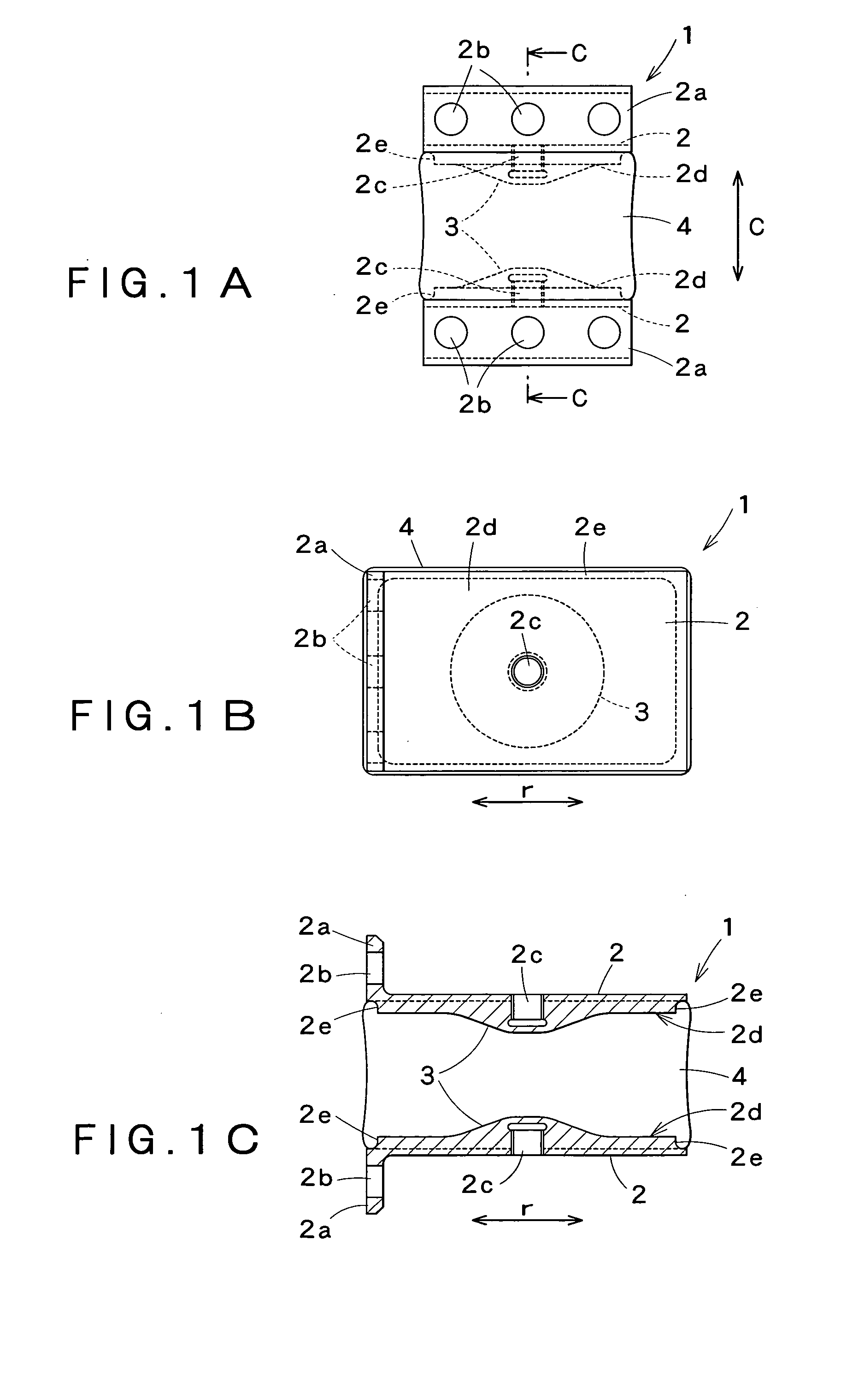
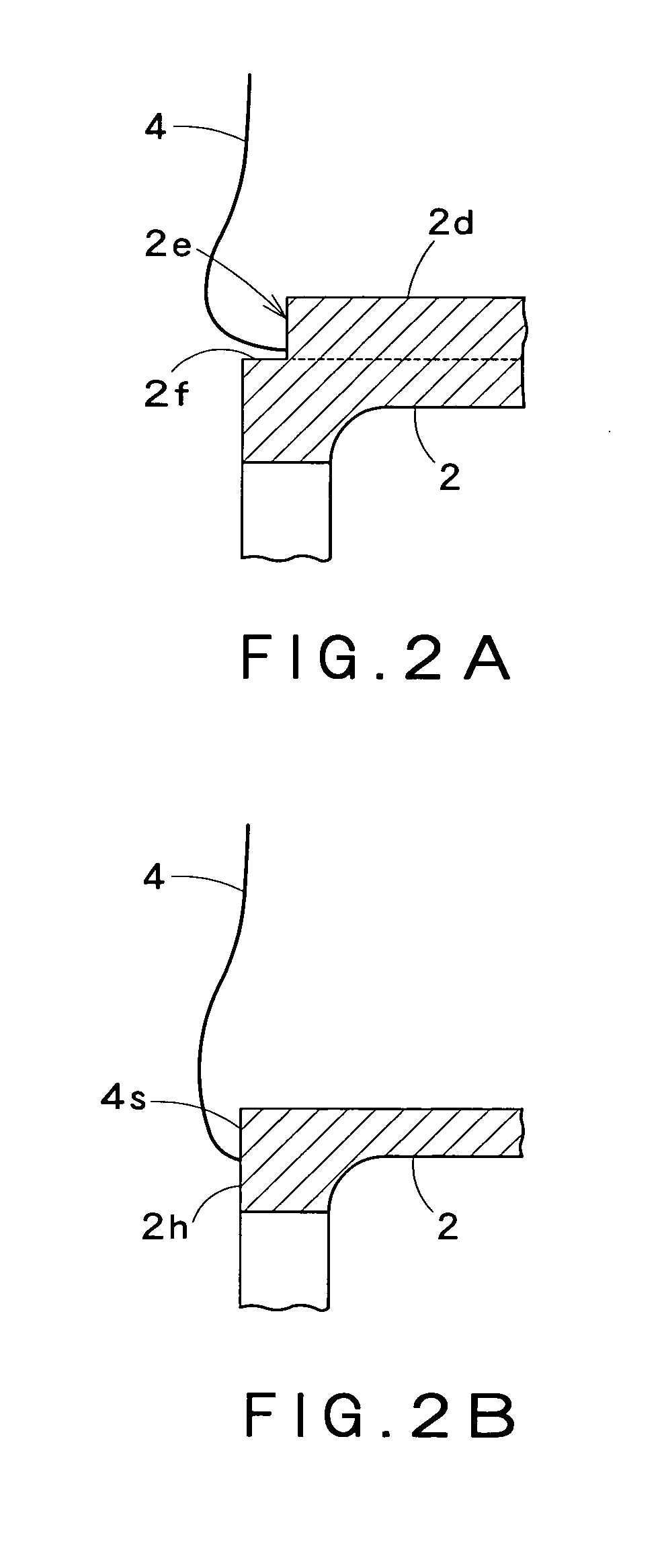
[0056] Rubber elements in preferred embodiments according to the present invention for a compression elastic coupling will be described in connection with the accompanying drawings.

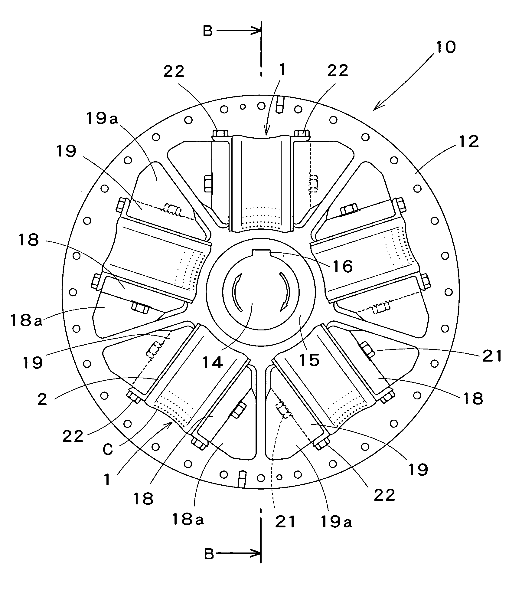
[0057] Referring to FIGS. 8 to 10, a compression elastic coupling 10 embodying the present invention is used for connecting a drive shaft, not shown, and a driven shaft 14 to transmit power from the drive shaft to the driven shaft 14. A flywheel 11 is formed integrally with a free end part of the drive shaft. An annular drive flange 12 is fastened to the flywheel 11 with a plurality of bolts 12a arranged in a circumferential direction c at equal angular intervals. The driven shaft 14 of the generator 13 is disposed coaxially with the drive shaft at a predetermined axial distance from the drive flange 12. The driven shaft 14 is supported for rotation. The driven shaft 14 is fitted in a tubular boss 15 formed integrally with a driven flange 17. A key 16 is inserted between the driven shaft 14 and the boss ...


PUM


Abstract

A rubber element according to the present invention includes a pair of mounting plates (2) attached respectively to a pair of rib surfaces of drive and driven ribs which are spaced and opposed to each other; and an elastic member (4) made of rubber held between the pair of mounting plates (2) which are spaced and opposed to each other and bonded to joining surfaces of the pair of mounting plates (2). The pair of mounting plates (2) are respectively provided with protrusions (3) protruding toward each other in central areas of the joining surfaces or lateral areas of the joining surfaces including the central areas and extending in a direction parallel to an axis about which flanges rotate.

Description

TECHNICAL FIELD [0001] The present invention relates to a rubber element for a compression elastic coupling for connecting, for example, the output shaft of a diesel engine and the input shaft of a driven device, provided with elastic rubber elements which are compressed when power is transmitted from the output shaft through the compression elastic coupling to the input shaft. BACKGROUND ART [0002] A known two-stage torsional elastic coupling disclosed in JP 7-27142 A (Reference 1) is a compression elastic coupling of this type. This known two-stage torsional elastic coupling includes inner elastic members having a low torsional rigidity and disposed near the center of the two-stage torsional elastic coupling and outer elastic members having a high torsional rigidity and disposed in a peripheral part of the two-stage torsional elastic coupling. Power of a low torque is transmitted from a drive flange through the inner elastic members to a driven member. When load on the two-stage t...

Claims


Application Information

Patent Timeline
Patent Type & Authority Applications(United States)
IPC IPC(8): F16D3/00F16F15/136F16D3/68F16F1/44
CPCF16F1/44F16D3/68F16D3/50
Inventor KAYAMOTO, SUSUMUHORIE, TAKASHI
Owner KAWASAKI HEAVY IND LTD
Why Eureka
Try Eureka