Cervical drill guide apparatus

a drill guide and cervical spine technology, applied in the field of cervical spine surgery, can solve the problems of reducing nerve function, affecting the healing effect of patients, and affecting the healing effect of patients, and avoiding the risk of screw pulling ou

Inactive Publication Date: 2007-04-26
K2M
View PDF15 Cites 60 Cited by
  • Summary
  • Abstract
  • Description
  • Claims
  • Application Information

AI Technical Summary

Problems solved by technology

Persons suffering from any of the above conditions typically experience extreme or debilitating pain and often times diminished nerve function.
Because the spine is routinely subject to mechanical loads which cycle during movement, a primary concern of physicians performing metal plate implantation surgeries, as well as of the patients in whom the implants are placed, is the risk of screw pullout.
Screw pullout occurs when the cylindrical portion of the bone that surrounds the inserted screw fails.
A bone screw that is implanted into the vertebrae perpendicular to the plate is particularly weak because the region of the bone that m

Method used


Image

  • Cervical drill guide apparatus
  • Cervical drill guide apparatus
  • Cervical drill guide apparatus

Examples


Embodiment Construction

[0035] While the presently disclosed cervical drill guide apparatus will be described more fully hereinafter with reference to the accompanying drawings, in which particular embodiments are shown, it is to be understood at the outset that persons skilled in the art may modify the apparatus herein described while achieving the functions and results of this apparatus. Accordingly, the descriptions that follow are to be understood as illustrative and exemplary of specific structures, aspects, and features within the broad scope of the present disclosure and not as limiting of such broad scope. Like numbers refer to similar features of like elements throughout.

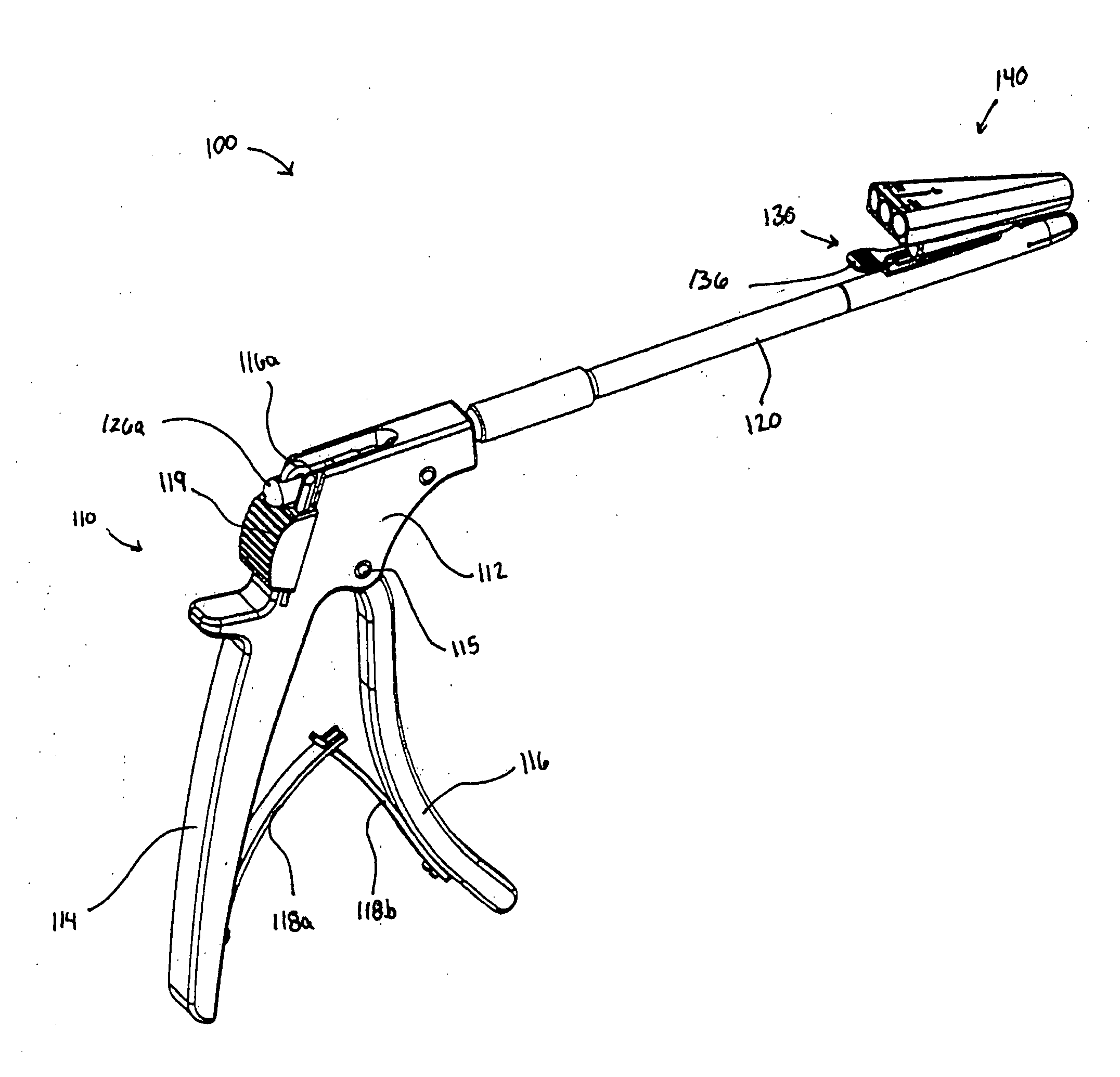
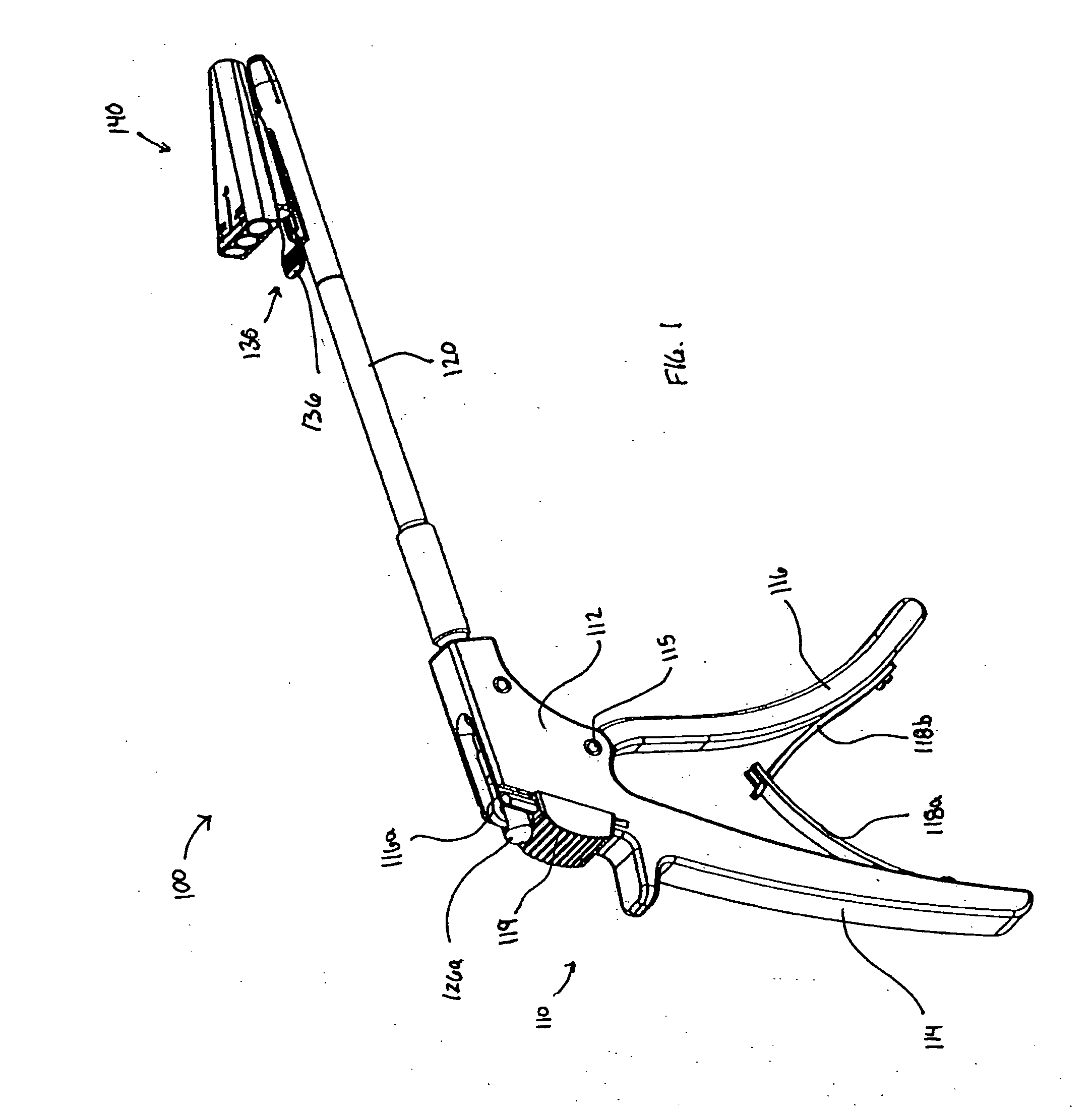
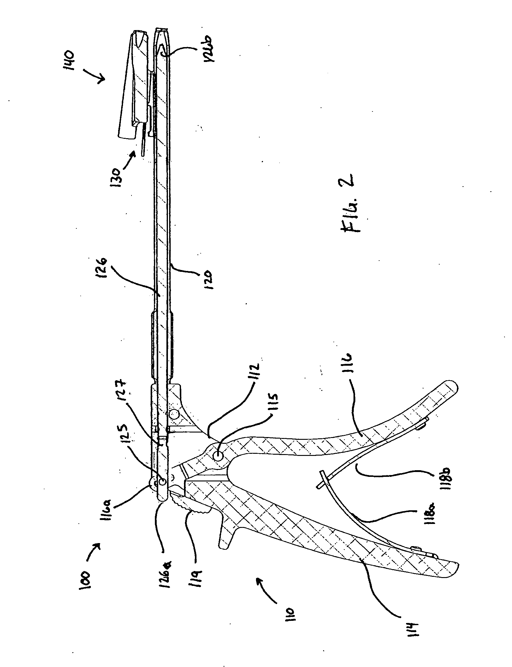
[0036] Referring to FIG. 1-3, an illustrative embodiment of the presently disclosed drill guide apparatus is illustrated therein and generally designated as drill guide 100. Drill guide 100 includes a handle assembly 110, an extension member 120, a mount assembly 130, and a removably attachable guide member 140. In this disclosur...


PUM


Abstract

A cervical drill guide apparatus includes a handle assembly having a housing and an extension member attached to one end of the housing. The handle assembly includes a fixed handle and a movable handle. A distal end of the extension member includes a plurality of fingers that are radially expandable or contractible in response to relative movement between an actuation shaft and the extension tube. The fingers are adapted for releasably engaging an opening in a plate. Additionally, a guide member is releasably attached to the distal end portion of the cervical drill guide apparatus. The guide member includes at least one opening therethrough for receiving a drill or other surgical instrumentation. The extension member may be rotatable in relation to the housing.

Description

CROSS-REFERENCE TO RELATED APPLICATIONS [0001] The present disclosure claims the benefit of and priority to Provisional Patent Application No. 60 / 721,484, filed on Sep. 29, 2005, the entire contents of which are hereby incorporated by reference.BACKGROUND [0002] 1. Technical Field [0003] The present disclosure relates generally to orthopedic spinal surgery and in particular to a cervical drill guide apparatus and methods for guiding a cervical drill, bone screw, or other instrumentation during spinal surgery. [0004] 2. Background of Related Art [0005] The spinal column is a complex system of bones and connective tissues that provide support for the human body and protection for the spinal cord and nerves. The adult spine is comprised of twenty-four vertebral bodies, which are subdivided into three areas, including seven cervical vertebrae, twelve thoracic vertebrae and five lumbar vertebrae. Between each vertebral body is an intervertebral disc that cushions and dampens the various ...

Claims


Application Information

Patent Timeline
IPC IPC(8): A61B17/60
CPCA61B17/1728A61B17/1757
Inventor HARRIS, PETERMCCLINTOCK, LARRYWALLENSTEIN, TODD
Owner K2M
Why Eureka
Try Eureka