Process and extruder nozzle for producing tubular extruded products

Inactive Publication Date: 2007-05-03
PELCZ ANTAL +2
View PDF2 Cites 10 Cited by
  • Summary
  • Abstract
  • Description
  • Claims
  • Application Information

AI Technical Summary

Benefits of technology

[0019] The primary object of the present invention is to eliminate the deficiencies mentioned above, that is, to create an improved solution by which extruded products,

Problems solved by technology

In practice, it is a serious problem to ensure a continuous uniform thermoplastic material flow.
A basic precondition for producing foil of uniform thickness is an uniform cooling of the blown foil hose exiting from the extruder nozzle; this means that the solidification points of the foil hose must be in the same horizontal plane, otherwise some parts of the product will extend and swell differently, therefore crawling may occur, which may lead to serious problems when rolling of the product.
Further application problems of the known foil blower extruder nozzles primarily come from the fact that extruder screws are generally installed in a horizontal arrangement, while foil blowing and thus the extruder nozzle has a vertical axis.
Although a substantially homogeneous material flow is generated at the extruder screw outlet, transition from the horizontal to the vertical direction frequently produces inhomogeneous parts in the plastic material flow, inevitably leading to finished product quality deterioration.
A further problem of the known extruder nozzles is that the structural units of the external and the inner components of the nozzle are fastened to each other, therefore their relative position (concentricity, coaxiality) is determined by the fit, as well as the shape and position tolerance of the respective component parts.
Accuracy, however, is limited by the present manufacturing technology, and

Method used


Image

  • Process and extruder nozzle for producing tubular extruded products
  • Process and extruder nozzle for producing tubular extruded products
  • Process and extruder nozzle for producing tubular extruded products

Examples


Example

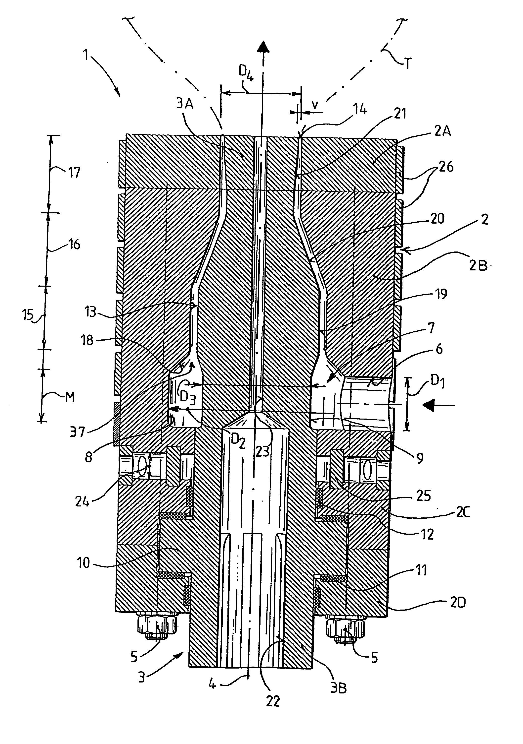
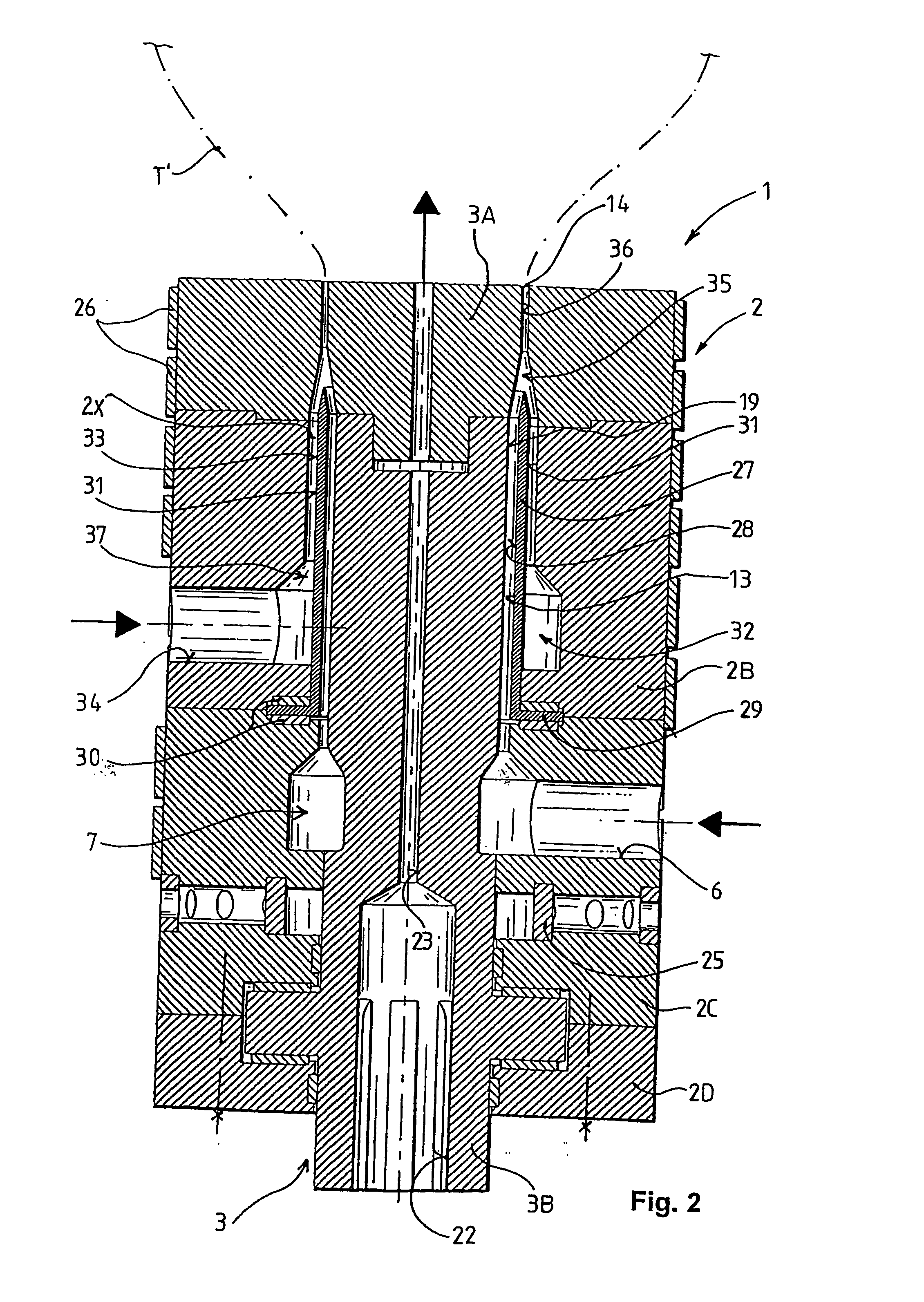
[0059] The second embodiment, shown in FIG. 2, of the extruder nozzle in accordance with the present invention is suitable for producing such two-layered foil hose. Similar parts in FIG. 2 have been designated with identical reference characters (as in FIG. 1) for simplicity and better comparability.

[0060] The extruder nozzle 1 as shown in FIG. 2 substantially corresponds to the solution according to FIG. 1 both in terms of structure and principle of operation. Said extruder nozzle 1 also comprises two main component parts: a standing outer nozzle component 2 and an inner nozzle core 3 rotatable embedded within said outer component 2. The external nozzle component 2 is axially divided, consisting of parts 2A, 2B, 2C, and 2D, respectively. The rotating nozzle core 3 is to be connected to a rotary drive in a known manner (not shown).

[0061] The standing external nozzle component 2 is also provided with a radial first inlet 6 to feed in a first melted plastic material flow under press...


PUM

PropertyMeasurementUnit
Electric chargeaaaaaaaaaa
Currentaaaaaaaaaa
Currentaaaaaaaaaa

Abstract

A process and an extruder nozzle for tubular products includes the steps of feeding pressurized material into an extruder nozzle through an inlet, and forcing this material flow through a duct formed between outer and inner nozzle components, and pressing the material flow through an annular aperture at the duct end. Material entering the extruder nozzle is distributed first by feeding into an annular expansion chamber whose cross-section is much greater than the inlet's. When the expansion chamber is completely filled with material whose pressure has become higher than the flow resistance of a homogenizing ring channel having a cross-section narrowed to and connected to the annular expansion chamber then in the homogenizing ring channel the material flow is forced to move across its entering direction, and is homogenized by the relative rotation of surfaces of the homogenizing ring channel. Helical forced movement leads the material to a drawing aperture.

Description

FIELD OF THE INVENTION [0001] The present invention relates to a process and an extruder nozzle for production of extruded tubular products, particularly blown tubular plastic foils (film hoses). Such plastic foils can be used e.g. for packaging of different products. BACKGROUND OF THE INVENTION [0002] There are processes and devices known in practice, used for producing blown foil hoses from thermoplastic materials using an extruder nozzle. Such nozzles are mainly vertically arranged, having a radial inlet for the thermoplastic material connected to an outlet of a generally horizontal extruder screw. In practice, it is a serious problem to ensure a continuous uniform thermoplastic material flow. The tubular product, mainly foil hose exiting from the annular extruder nozzle is stretched to reach a required diameter and wall thickness. In order to provide with an air chamber required for blowing, the foil hose is led through two pinch rolls, which also exert a force required for take...

Claims


Application Information

Patent Timeline
IPC IPC(8): B29C47/20A21C11/16B29C35/02B29C47/06B29C47/86B29C48/32B29C48/33B29C48/335B29C48/34
CPCA21C11/16B29C35/0255B29C47/0023B29C47/0026B29C47/0057B29C47/025B29C47/065B29C47/24B29C47/26B29C47/268B29C47/28B29C47/86B29C2035/0211B29L2009/00B29L2023/001B29C48/0018B29C48/09B29C48/10B29C48/154B29C48/21B29C48/33B29C48/335B29C48/338B29C48/86B29C48/865B29C48/34
Inventor PELCZ, ANTALILLES, TAMASSZABO, LAJOS
Owner PELCZ ANTAL
Why Eureka
Try Eureka