Front fork

Inactive Publication Date: 2007-05-03
SHOWA CORP
View PDF5 Cites 3 Cited by
  • Summary
  • Abstract
  • Description
  • Claims
  • Application Information

AI Technical Summary

Benefits of technology

[0010] An object of the present invention is to simplify a finish of a lower end surface of a damper cylinder as well as making a thickness dimension of the damper cylinder thin, when forming the damper cylinder in a standing manner in a bottom portion of an axle side tube, in a front fork.

Problems solved by technology

(1) Since the damper cylinder is provided with a groove cross section for forming the stopper ring in addition to a real cross section sufficient for securing the necessary tensile strength of a front fork, it is difficult to make the thickness dimension of the damper cylinder thin.
Accordingly, it is difficult to make the thickness dimension of the damper cylinder thin.

Method used


Image

  • Front fork
  • Front fork
  • Front fork

Examples


Embodiment Construction

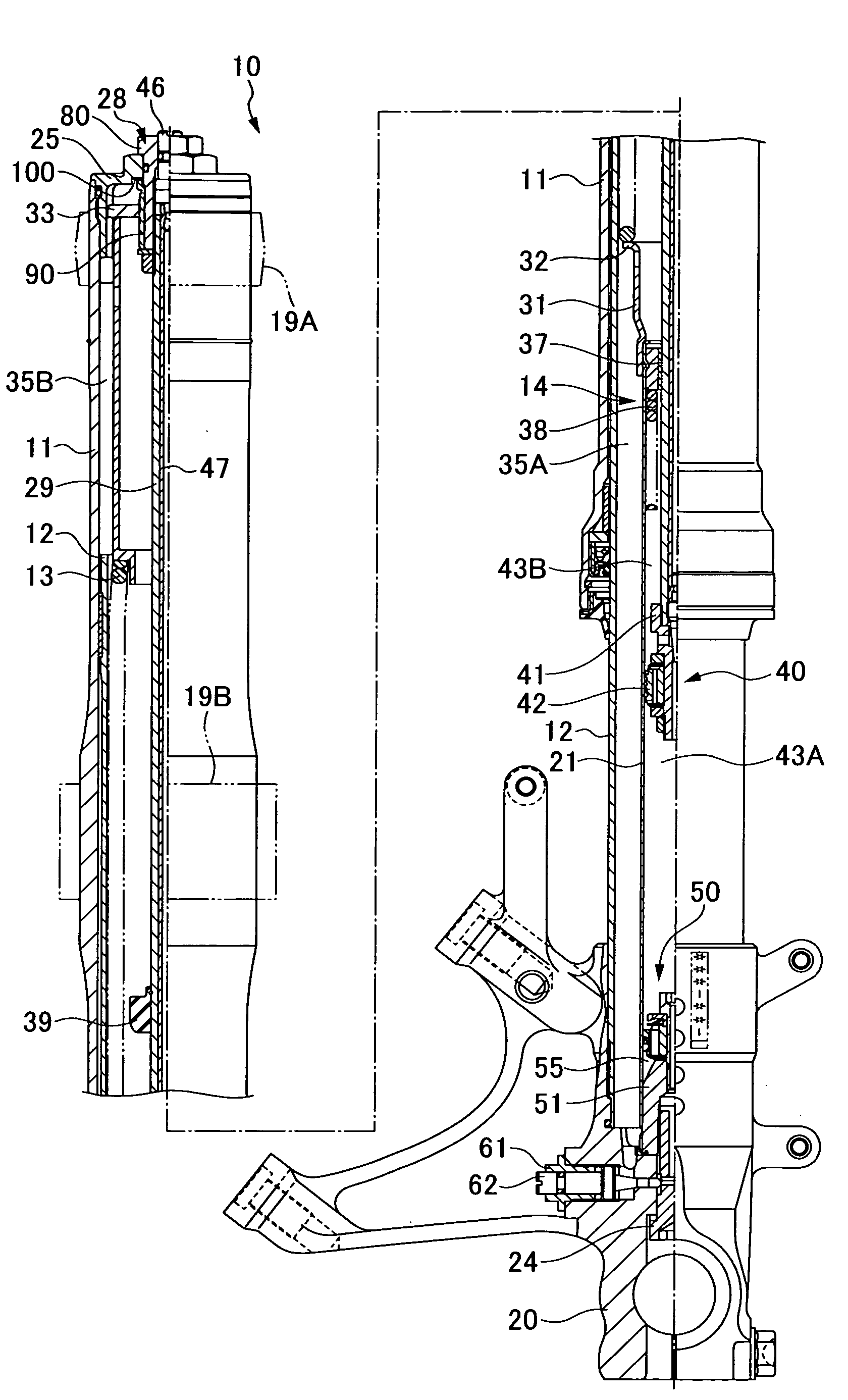
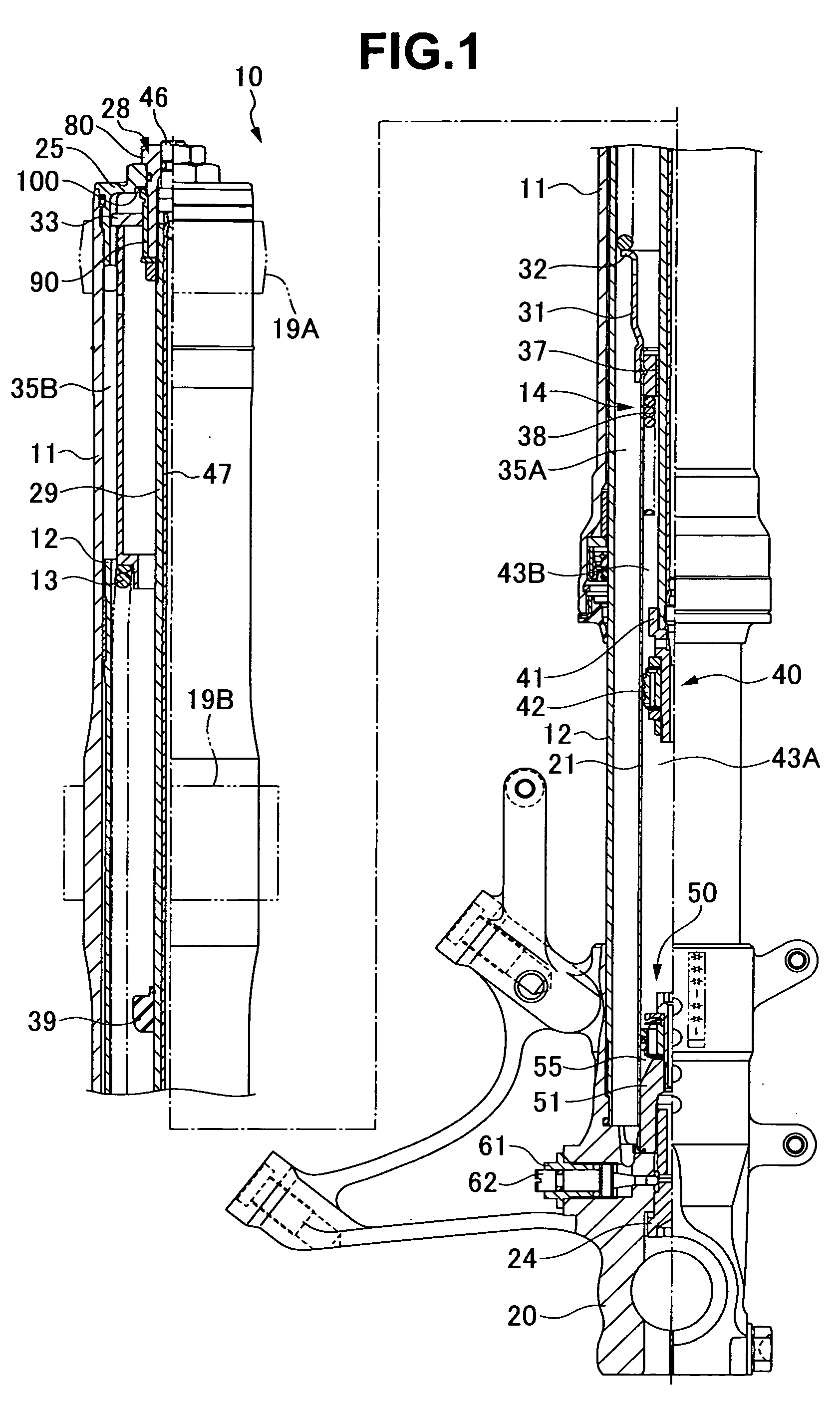
[0027] A front fork 10 is structured, as shown in FIGS. 1 to 4, such that a vehicle body side outer tube (a vehicle body side tube) 11 is slidably fitted to an axle side inner tube (an axle side tube) 12 so as to be inverted. A suspension spring 13 is placed between both the tubes 11 and 12, and a single cylinder type damper 14 is incorporated in an erect manner.

[0028] A bush 15, an oil seal 16 and a dust seal 17 with which an outer peripheral portion of the inner tube 12 is brought into slidable contact are fitted to an inner peripheral portion of a lower end of the outer tube 11, and a bush 18 with which an inner peripheral portion of the outer tube 11 is brought into slidable contact is fitted to an outer peripheral portion of an upper end of the inner tube 12.

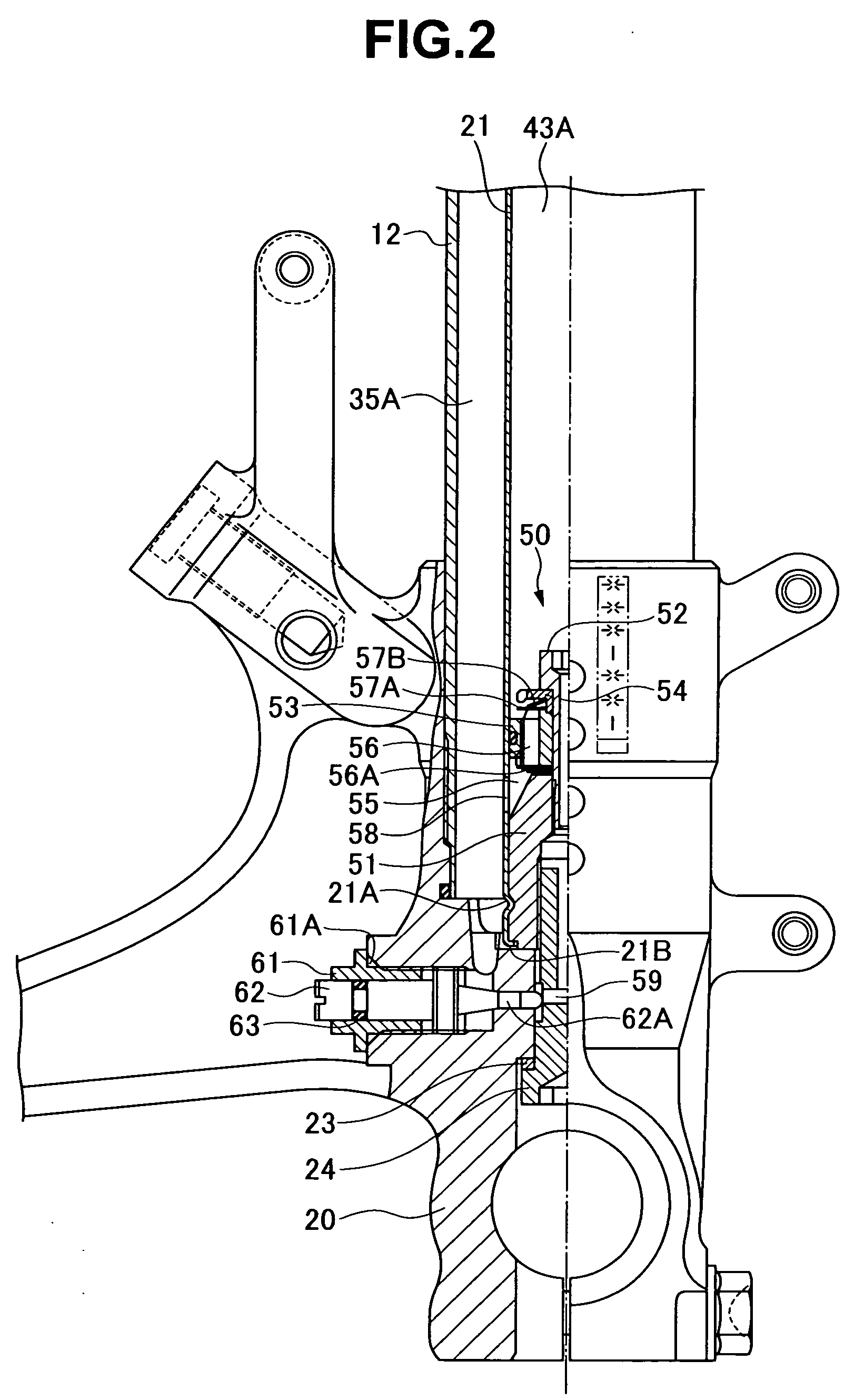
[0029] The outer tube 11 is supported to a vehicle body side via an upper bracket 19A and a lower bracket 19B, and the inner tube 12 is coupled to an axle via an axle bracket 20.

[0030] A lower end portion of a damper cyl...


PUM


Abstract

In a front fork, a bottom piece is inserted to an inner periphery of a lower end portion of a damper cylinder, and the lower end portion of the damper cylinder is fixed by caulking to an outer periphery of the bottom piece, and a bottom bolt locked into a bottom portion of the axle side tube is screwed from an outer side with the bottom piece, whereby a lower surface of the bottom piece is fastened to a bottom surface of an axle side tube.

Description

BACKGROUND OF THE INVENTION [0001] 1. Field of the Invention [0002] The present invention relates to a front fork of a motor cycle or the like. [0003] 2. Description of the Related Art [0004] In a front fork, there is a structure in which an axle side tube is slidably fitted to a vehicle body side tube, and a damper cylinder having a bottom piece is provided in a standing manner in a bottom portion of the axle side tube. [0005] As a fixing structure for the bottom piece, Japanese Patent Application Laid-open No. 2003-172392 (patent document 1) describes the followings. A lower end surface of a damper cylinder is brought into contact with a bottom portion (an axle bracket or the like) of the axle side tube. A bottom piece is inserted to an inner periphery of a lower end portion of the damper cylinder. The bottom piece is locked to a stopper ring in an inner periphery of a lower end of the damper cylinder. A bottom bolt engagedly inserted to the bottom portion of the axle side tube fr...

Claims


Application Information

Patent Timeline
IPC IPC(8): F16F7/00
CPCB62K25/08
Inventor MURAKAMI, YOSUKE
Owner SHOWA CORP
Why Eureka
Try Eureka