
Hard top convertible roof

a convertible roof and hard top technology, applied in the field of vehicles, can solve the problems of limited space, inhibiting or preventing the use of rigid panels for convertible roofs, and limited storage space in vehicles for stowing convertible roofs in a retracted position, and achieve the effect of refinement or polishing the imag

Inactive Publication Date: 2007-05-03
SPECIALTY VEHICLE ACQUISITION
View PDF1 Cites 12 Cited by
  • Summary
  • Abstract
  • Description
  • Claims
  • Application Information

AI Technical Summary

Benefits of technology

[0003] Vehicles having a convertible roof provide a pleasurable driving experience. A hard top retractable roof (convertible top) using rigid panels may provide a finished appearance that resembles a non-convertible top version of the same vehicle. Additionally, the use of hard top panels may provide a more refined or polished image relative to the use of a soft top convertible roof. Additionally, the hard top panels may have the same appearance or finish as the other body panels of the vehicle.
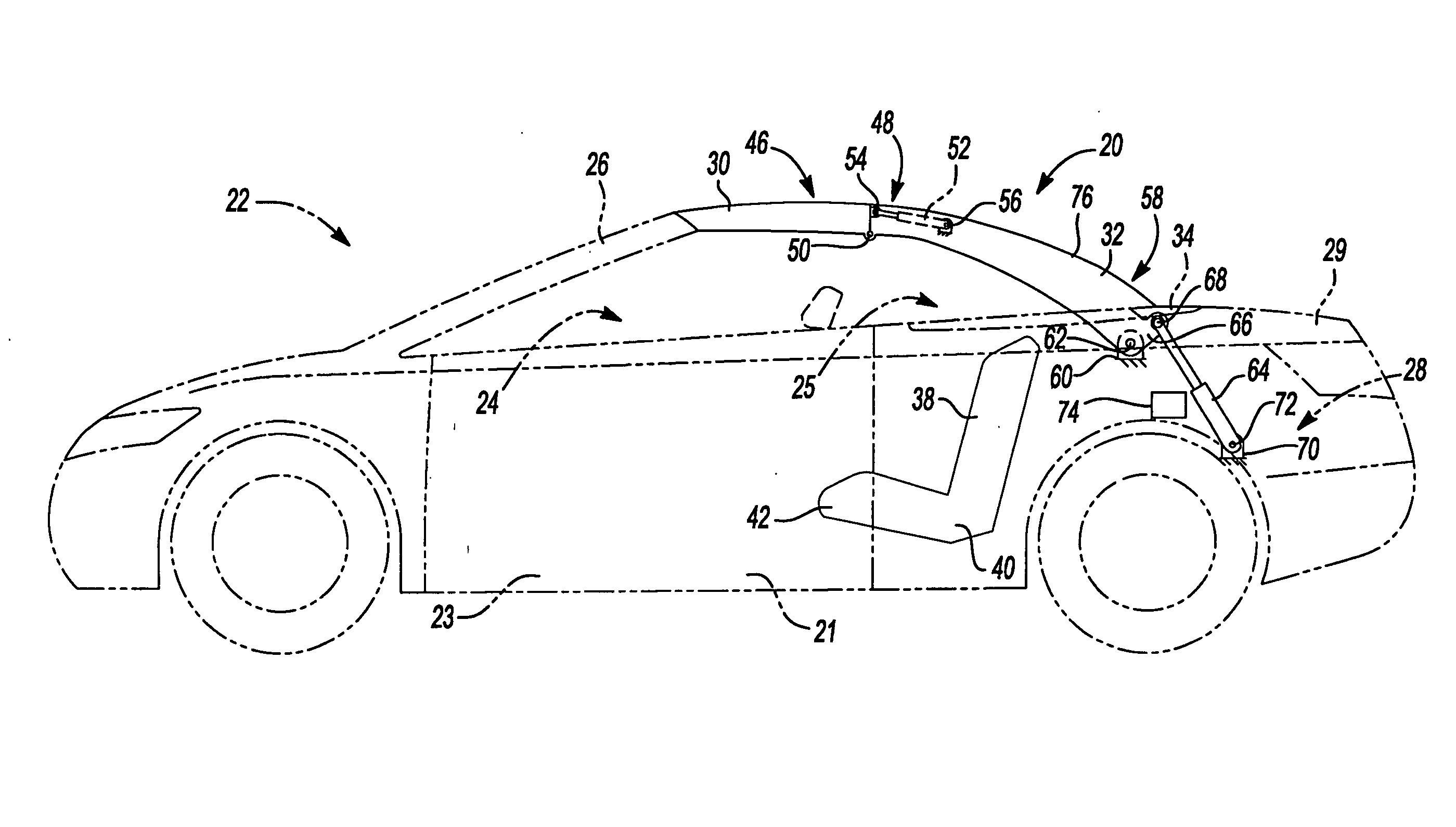
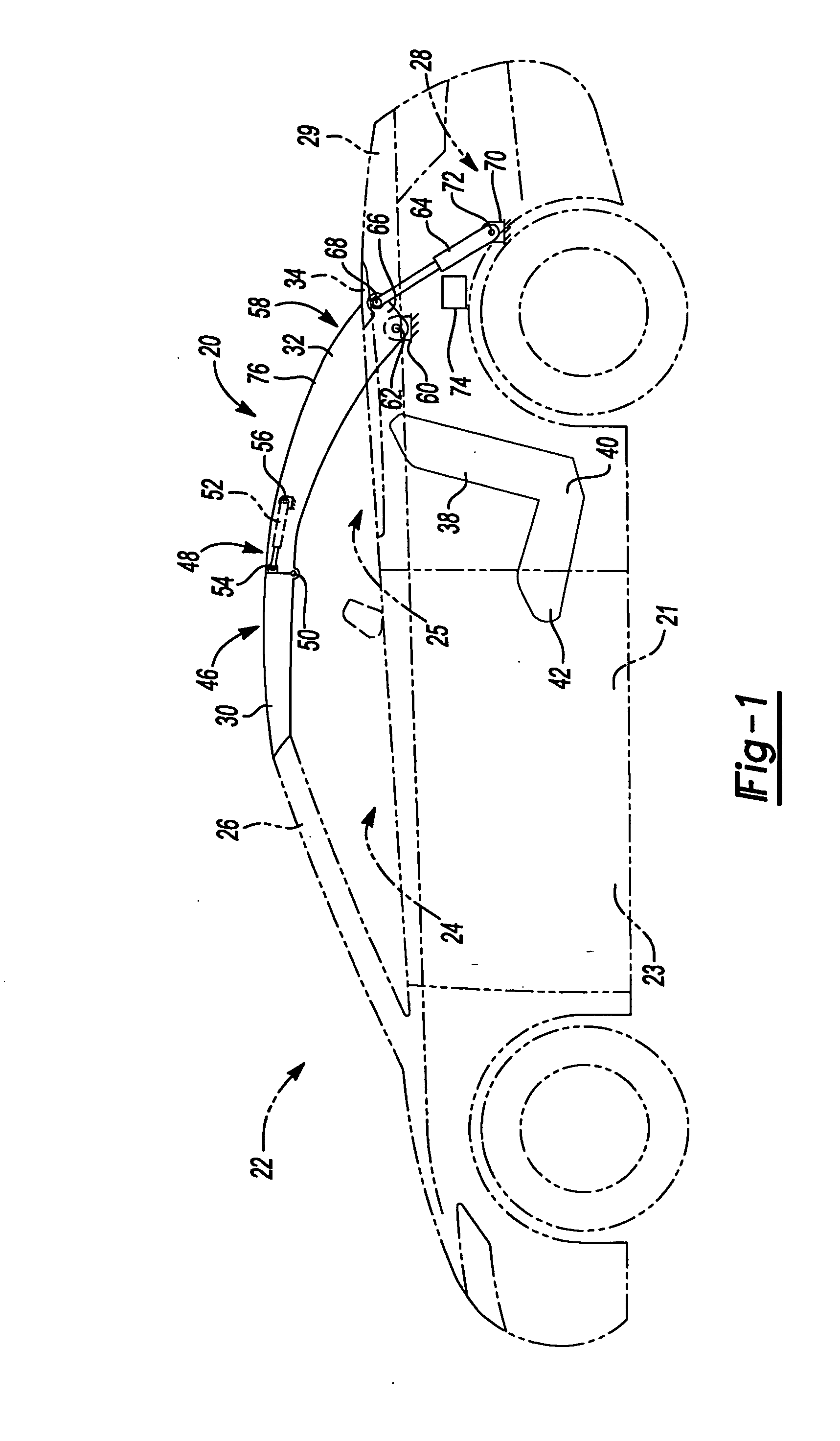
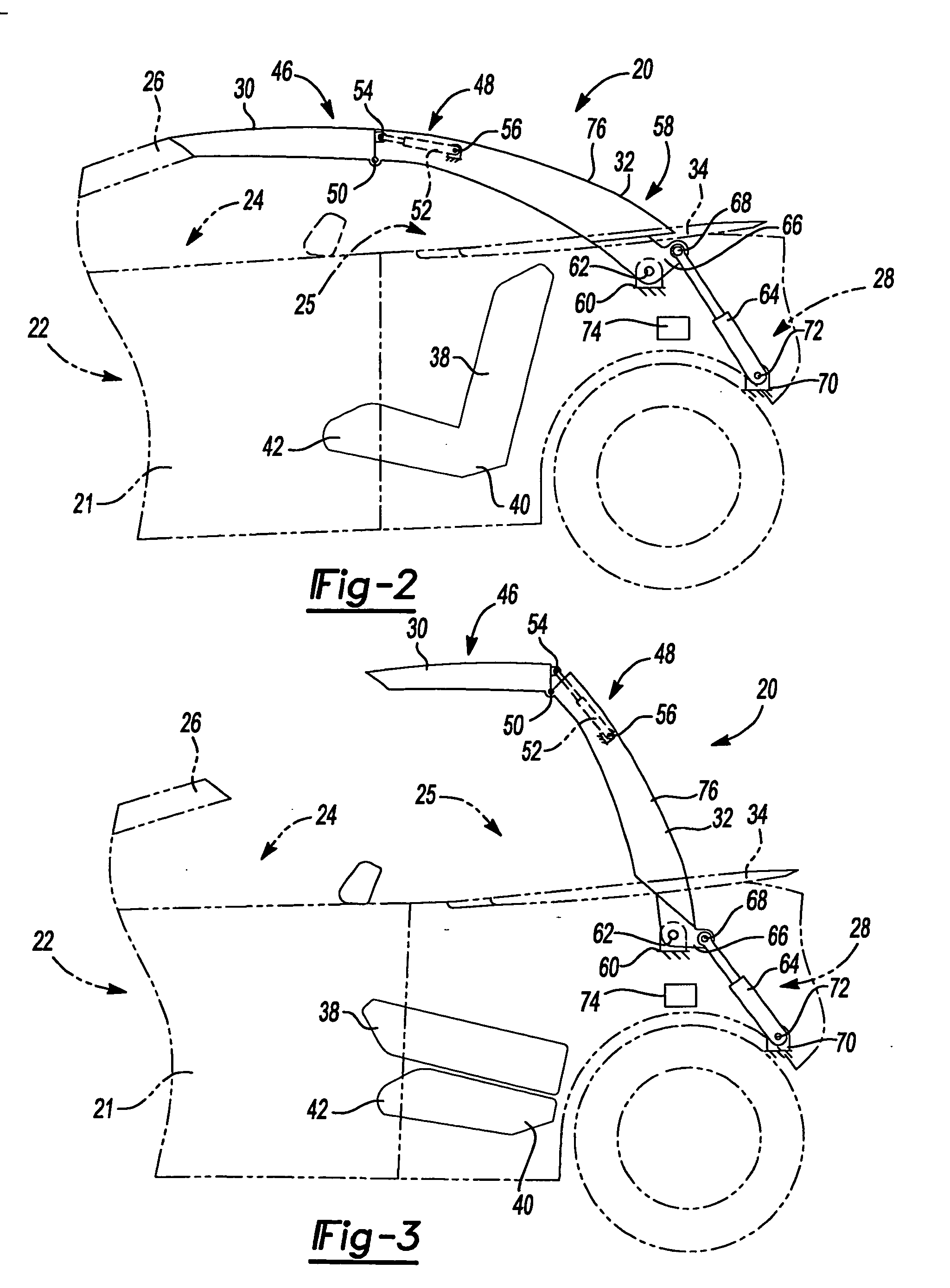
[0005] A convertible top according to the present invention can advantageously utilize a portion of the rear seating area of the vehicle to stow the panels when in the retracted position. When the convertible top is in the raised position, the rear passenger seating area is not impeded such that both the front and rear seating areas may be utilized. One of the panels can form a cover for the convertible top when in the retracted position. This ability allows the convertible top to advantageously be self-covering. The initial movement of the rearmost panel can be a dropping motion toward the rear passenger seating area. The initial movement can advantageously avoid the use of a moveable tonneau cover on the vehicle. The movement of a rearmost panel and a forward panel can occur simultaneously. The simultaneous movement can speed up the raising and retracting process. A fixed length link can be utilized to guide the movement of a forward panel during movement of the rearmost panel. The fixed length link can advantageously simply the actuation of the roof panels between the raised and retracted positions. The rearmost panel can be moved to a generally vertical position during the raising and retracting process. The generally vertical position can advantageously allow for a large operating window for the convertible top without encroaching undesirably into a front passenger seating area.

Problems solved by technology

The stowage space in a vehicle for stowing the convertible roof in a retracted position, however, may be limited.
This limited space may inhibit or prevent the use of rigid panels for the convertible roof.

Method used


Image

  • Hard top convertible roof
  • Hard top convertible roof
  • Hard top convertible roof

Examples


Embodiment Construction

[0023] The following description is merely exemplary in nature and is in no way intended to limit the invention, its application, or uses.

[0024] In describing the present teaching, the terms “fore” and “aft”, “front” and “back”, “clockwise” and “counterclockwise”, and “forward” and “rearward” may be used to describe the relative movement and components of the present teachings, such usage refers to the orientation of the components when the convertible roof is in the fully raised position and the orientation shown in the views depicted. When describing the various components and linkages of the convertible roofs according to the present teachings, it should be appreciated that the components and linkages are generally symmetrical about a longitudinal, fore-and-aft centerline (not shown) of the vehicle. For brevity, only one side of the convertible roof and the associated linkages may be shown and / or discussed, however, it should be understood that opposite side components and linka...


PUM


Abstract

A convertible top vehicle according to the present invention advantageously utilizes a portion of the rear seating area of the vehicle to stow the roof when in the retracted position. When the convertible top is in the raised position, the rear passenger seating area is not impeded such that both the front and rear seating areas may be utilized.

Description

CROSS-REFERENCE TO RELATED APPLICATIONS [0001] This application claims the benefit of U.S. Provisional Application No. 60 / 731,305, filed on Oct. 28, 2005. The disclosure of the above application is incorporated herein by reference.FIELD OF THE INVENTION [0002] The present invention relates to vehicles and, more particularly to vehicles having a hard top convertible roof. BACKGROUND AND SUMMARY OF THE INVENTION [0003] Vehicles having a convertible roof provide a pleasurable driving experience. A hard top retractable roof (convertible top) using rigid panels may provide a finished appearance that resembles a non-convertible top version of the same vehicle. Additionally, the use of hard top panels may provide a more refined or polished image relative to the use of a soft top convertible roof. Additionally, the hard top panels may have the same appearance or finish as the other body panels of the vehicle. [0004] The stowage space in a vehicle for stowing the convertible roof in a retrac...

Claims


Application Information

Patent Timeline
IPC IPC(8): B60J7/08
CPCB60J7/145B60J7/146B60J7/148B60J7/201
Inventor CORDER, GEORGE A.DOWDEY, CHRISTOPHER C.THEODORE, CHRIS P.GARSKA, BRADLEY R.
Owner SPECIALTY VEHICLE ACQUISITION
Learn More