Light-emitting device, driving circuit, driving method, and electronic apparatus

a technology of light-emitting devices and driving circuits, applied in static indicating devices, instruments, printing, etc., can solve problems such as brightness variation caused by errors (deviations) in the characteristics of individual light-emitting elements, and achieve the effect of preventing a variation in the brightness (grayscale value) of a light-emitting elemen

Inactive Publication Date: 2007-05-03
ELEMENT CAPITAL COMMERCIAL CO PTE LTD
View PDF5 Cites 7 Cited by
  • Summary
  • Abstract
  • Description
  • Claims
  • Application Information

AI Technical Summary

Benefits of technology

[0008] An advantage of some aspects of the invention is that it provides a technique for preventing a variation in the brightness (grayscale value) of a light-emitting element for a long time.
[0010] With this construction, since the first and second coefficients are selected so that the peak light amounts (luminous energies) of the light-emitting elements when the same grayscale value is designated by the grayscale data are almost equal to one another, it is possible to suppress the variation in the brightnesses (grayscale values) of the plurality of light-emitting elements. Further, since the first and second coefficients are selected so that the variations in the light emission characteristics of the plurality of light-emitting elements driven by the driving signals from the driving unit are substantially equal to one another, it is possible to suppress the difference between the light-emitting elements from increasing over time. Therefore, an effect of suppressing the variation in the brightnesses (grayscale values) can be maintained for a long time.
[0017] An electronic apparatus according to a second aspect of the invention includes the light-emitting element according to first aspect of the invention. A typical example of the electronic apparatus is an image forming apparatus using the light-emitting device according to the first aspect of the invention as an exposing device (exposing head). The image forming apparatus includes an image carrier with an image forming surface where a latent image is formed by exposing, the light-emitting device according to the first aspect of the invention exposing the image forming surface, and a developing device forming a toner image by depositing a developer (for example, toner) to the latent image. With the light-emitting device according to the first aspect of the invention, since an effect of suppressing the variation in the light amount (grayscale value) of each light-emitting element is maintained for a long time. Therefore, an image forming apparatus using the light-emitting device can form images with a uniform quality on recording materials for a long time.
[0019] According to a third aspect of the invention, a circuit of driving a light-emitting device is provided. The light-emitting device includes a plurality of light-emitting elements whose light emission amount is controlled according to a current value and a pulse width of a driving signal. In each of he light-emitting elements, a variation in the light emission characteristic when the pulse width is changed and the current value of the driving signal is fixed is different from a variation in the light emission characteristic when the current value is changed and the pulse width of the driving signal is fixed. The driving circuit includes: a storage unit that stores first and second coefficients for every light-emitting element; a pulse width determining unit that determines the pulse width of the driving signal supplied to each light-emitting element on the basis of the first coefficient for the corresponding light-emitting element stored in the storage unit and a grayscale value designated by grayscale data for the corresponding light-emitting element; a current value determining unit that determines the current value of the driving signal supplied to each light-emitting element on the basis of the second coefficient for the corresponding light-emitting element stored in the storage unit; and a driving unit that supplies the driving signal having the current value determined by the current value determining unit within the pulse width determined by the pulse width determining unit to the corresponding light-emitting element. In the driving circuit, the first and second coefficients stored in the storage unit are selected so that the light amounts of the individual light-emitting elements when the same grayscale value is designated by the grayscale data to the light-emitting elements are almost equal to one another and the variations in the light emission characteristics of the plurality of light-emitting elements driven by the driving signals from the driving unit are substantially equal to each other. The driving circuit makes it possible to suppress the variation in the light amount (grayscale value) of each light-emitting element for a long time.

Problems solved by technology

In such a light-emitting device, a brightness variation caused by errors (deviations) in the characteristics of individual light-emitting elements becomes a problem.

Method used


Image

  • Light-emitting device, driving circuit, driving method, and electronic apparatus
  • Light-emitting device, driving circuit, driving method, and electronic apparatus
  • Light-emitting device, driving circuit, driving method, and electronic apparatus

Examples


first modification

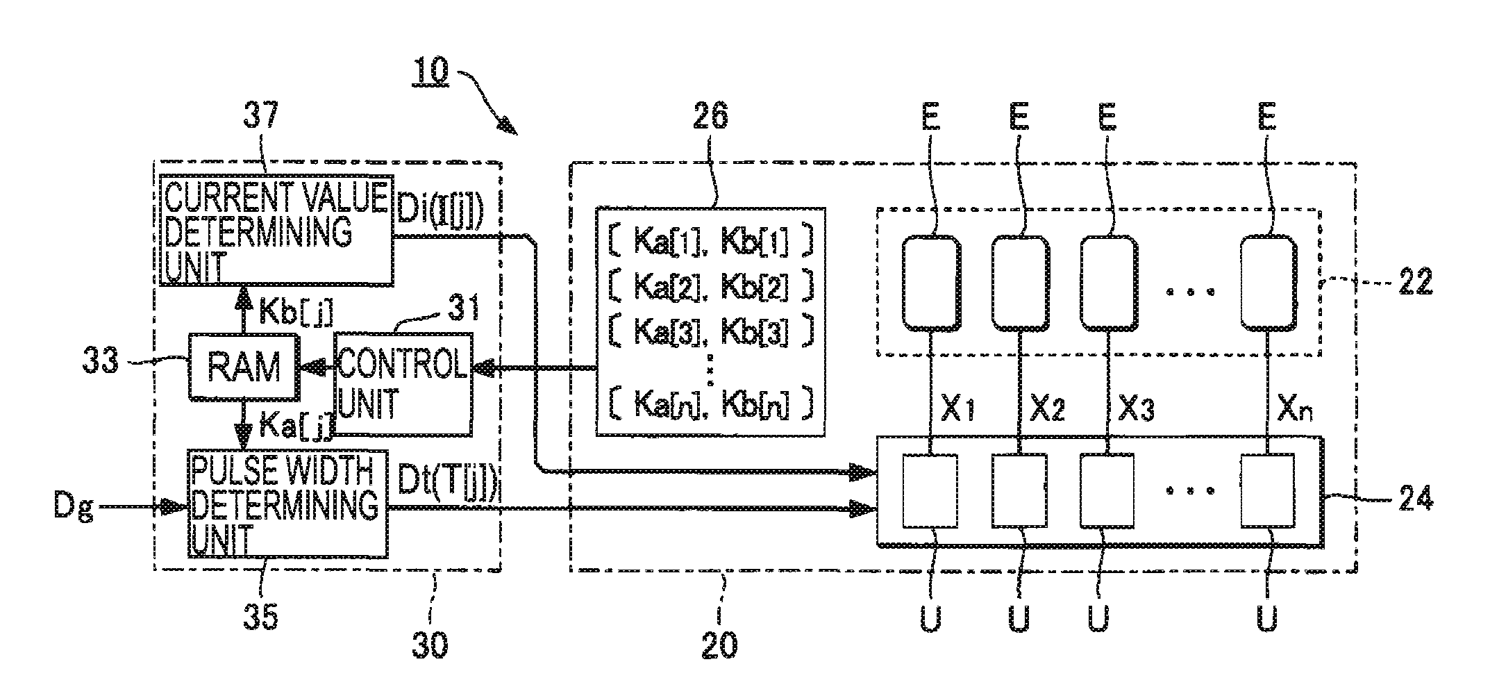
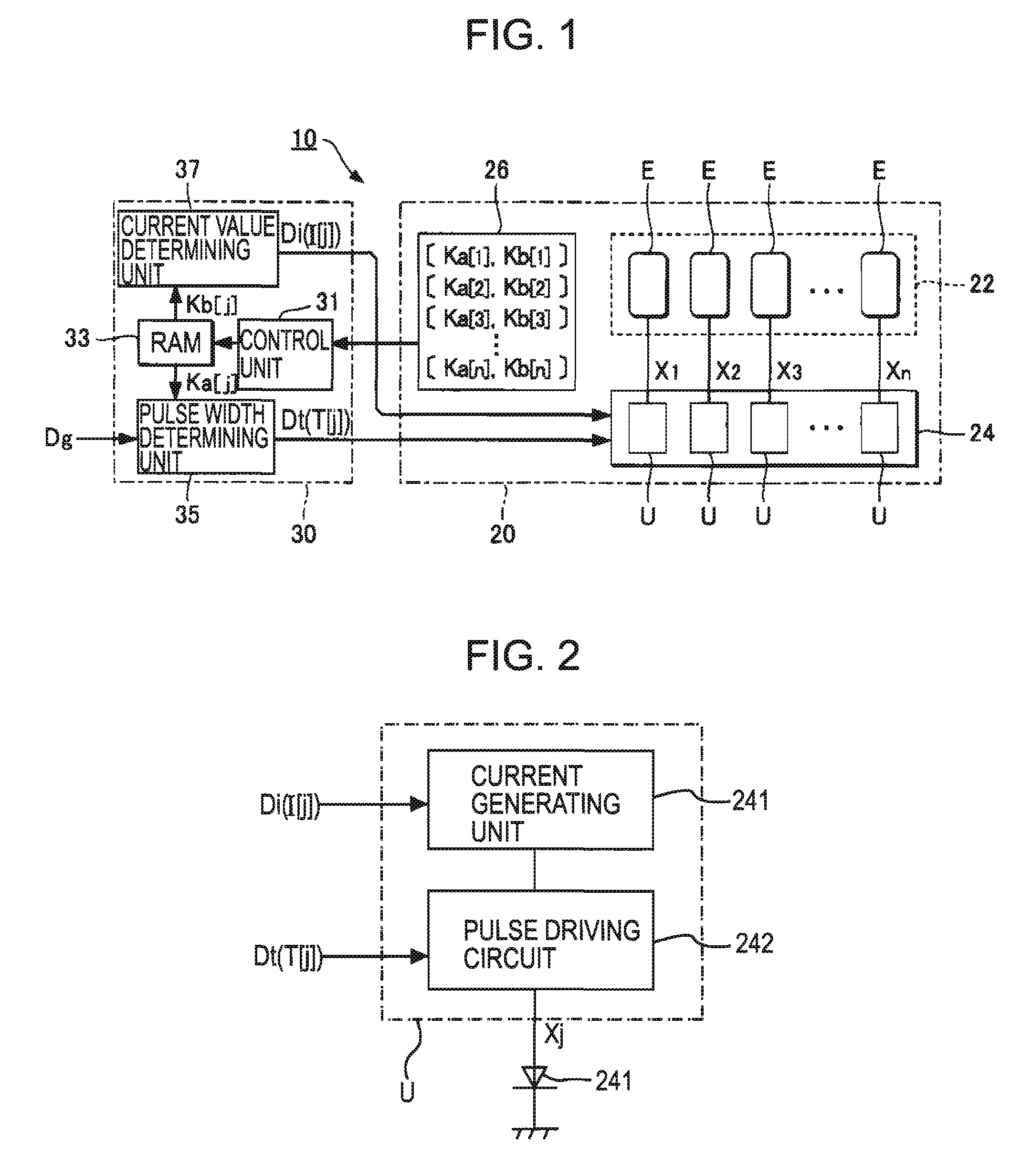
[0064] In the above-mentioned embodiment, the storage device 26 for storing the correction coefficients Ka[j] and Kb[j] is provided in the head module 20. However, the position where the storage device 26 is provided may be appropriately changed. For example, the storage device 26 may be built in the controller 30. The correction coefficient Ka[j] or Kb[j] is a numeral value depending on the characteristics of each light-emitting element E. Therefore, when producing the light-emitting device 10 including the controllers 30 with the built-in storage device 26 in large quantities, it is required to strictly manage the correspondence between the head module 20 and the controller 30 for every light-emitting device 10. In contrast, in the embodiment of FIG. 1, the storage device 26 is provided together with the light-emitting unit 22 in the head module 20. Therefore, even when the characteristics of the individual light-emitting elements E are different from one another for every light-e...

second modification

[0065] In the above-mentioned embodiment and the first modification, the controller 30 sets the pulse width T[j] and the current value I[j] according to the correction coefficients (Ka[j] and Kb[j]). However, at least one of the pulse width T[j] and the current value I[j] may be set by the head module 20. For example, the pulse width T[j] according to th-e correction coefficient Ka[j] is computed by the controller 30, and the current value I[j] according to the correction coefficient Kb[j] is determined by the head module 20. However, in the invention, it is not indispensable to separately configure the head module 20 and the controller 30. For example, a circuit having the same effects and functions as the controller shown in FIG. 1 may be provided in the head module 20.

third modification

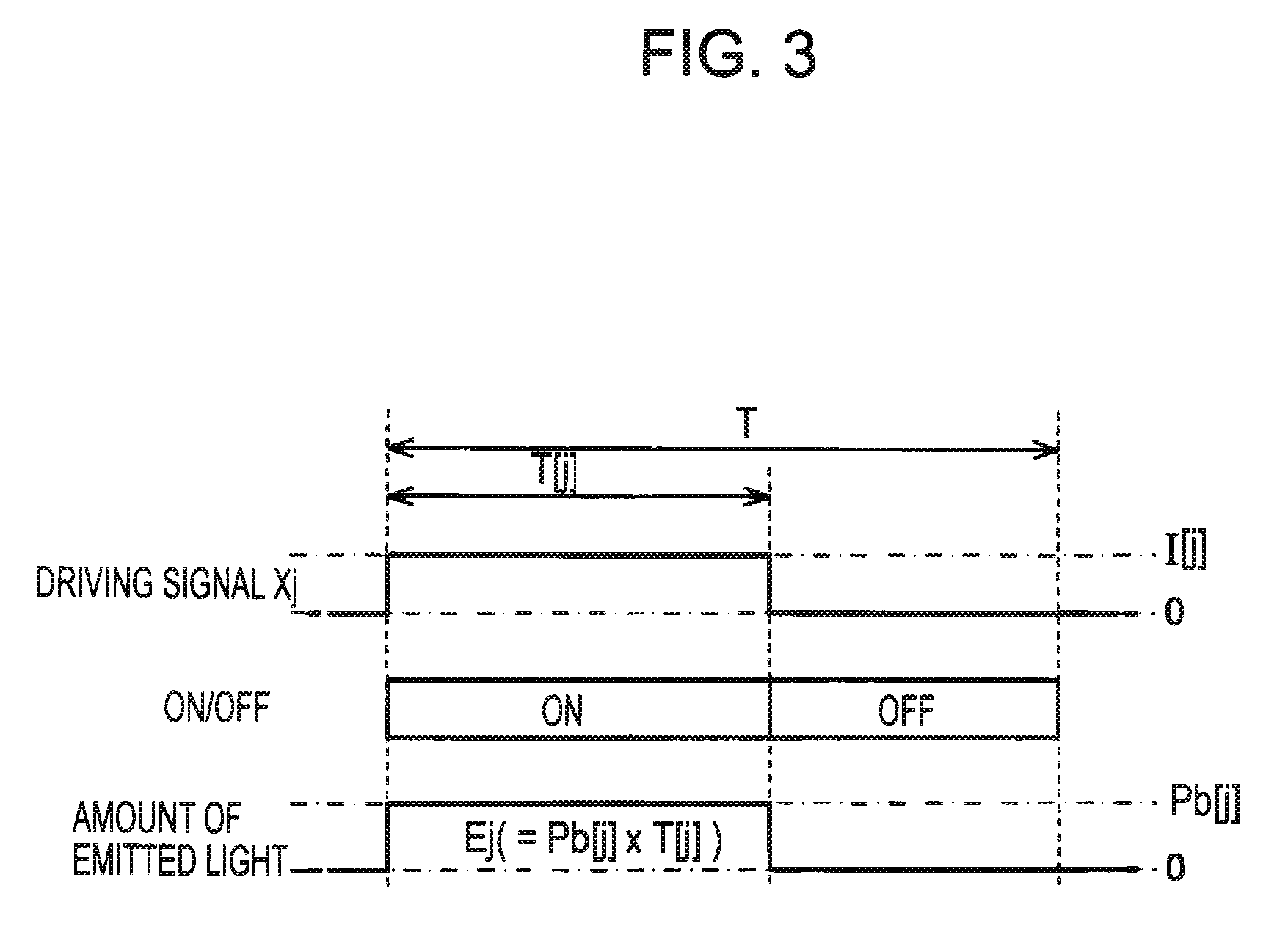
[0066] The method of setting the pulse width T[j] on the basis of the correction coefficient Ka[j] and the method of setting the current value I[j] on the basis of the correction coefficient Kb[j] are not limited to the above-mentioned embodiments and modifications. In the above-mentioned embodiments and modifications, the pulse width T[j] is computed by multiplying the grayscale value of the grayscale data Dg by the correction coefficient Ka[j]. However, the pulse width T[j] may be computed by other computations. Further, in the above-mentioned embodiments and modifications, the correction coefficient Ka[j] of Equation 8a is stored in the storage device 20. However, the pulse width T[j] of Equation 7a may be stored in the storage device 26. In this construction, the pulse width determining unit 35 determines the pulse width T[j] of the driving signal Xj by adjusting the pulse width Tb[j] read from the storage device 26 on the basis of the grayscale data Dg. Furthermore, the peak li...


PUM


Abstract

A light-emitting device includes: a plurality of light-emitting elements whose luminous energy is controlled according to a current value and a pulse width of a driving signal; a storage unit that stores first and second coefficients for every light-emitting element; a pulse width determining unit that determines the pulse width of the driving signal supplied to each light-emitting element on the basis of the first coefficient for the corresponding light-emitting element stored in the storage unit and a grayscale value designated for the corresponding light-emitting element by grayscale data; a current value determining unit that determines a current value of the driving signal supplied to each light-emitting element on the basis of the second coefficient for the corresponding light-emitting element stored in the storage unit; and a driving unit that supplies the driving signal having the current value determined by the current value determining unit within the pulse width determined by the pulse width determining unit to the corresponding light-emitting element. In the light-emitting device, a variation in the light emission characteristic of each light-emitting element when the pulse width is changed and the current value of the driving signal is fixed is different from a variation in the light emission characteristic thereof when the current value is changed and the pulse width of the driving signal is fixed, and the first and second coefficients stored in the storage unit are selected so that the peak light amount of the individual light-emitting elements when the same grayscale value is designated by the grayscale data are almost equal to one another and variations in the light emission characteristics of the plurality of light-emitting elements driven by the driving signals from the driving unit are substantially equal to one another.

Description

BACKGROUND [0001] 1. Technical Field [0002] The present invention relates to a technique of controlling a light-emitting device such as an organic light-emitting device (hereinafter, referred to as ‘OLED’). [0003] 2. Related Art [0004] Light-emitting devices for controlling light-emitting elements to desired brightness levels depending on pulse widths or current values of signals (hereinafter, referred to as ‘driving signals’ provided to the light-emitting elements have been proposed. In such a light-emitting device, a brightness variation caused by errors (deviations) in the characteristics of individual light-emitting elements becomes a problem. Techniques for suppressing such a brightness variation by correcting current values of driving signals depending on real characteristics of light-emitting elements are disclosed in, for example, JP-A-2005-103914 and JP-A-2005-81696. Also, techniques for suppressing such a brightness variation by correcting pulse widths of driving signals d...

Claims


Application Information

Patent Timeline
Patent Type & Authority Applications(United States)
IPC IPC(8): G09G3/30B41J2/44B41J2/45H05B44/00B41J2/455G09G3/20H01L33/00
CPCG06K15/1209G06K15/1247G09G3/2081G09G3/3208G09G3/342G09G2320/0233G09G2320/0285G09G2320/0295G09G2320/043G09G2320/045G09G2360/147
Inventor MIYAZAWA, TAKAO
Owner ELEMENT CAPITAL COMMERCIAL CO PTE LTD
Why Eureka
Try Eureka