Automated mesh creation method for injection molding flow simulation

a mesh creation and flow simulation technology, applied in the field of mesh creation methods, can solve the problems of poor mesh quality for injection molding flow simulation applications, affecting the interpretation of these analysis results and the predictive capability of cae software, and high distortion of types of meshes, so as to improve the quality of the plurality

Inactive Publication Date: 2007-05-03
CORETECH SYST
View PDF8 Cites 16 Cited by
  • Summary
  • Abstract
  • Description
  • Claims
  • Application Information

AI Technical Summary

Benefits of technology

[0015] In one embodiment of the present invention, the present invention refines the plurality of surface meshes is performed according to the thickness and/or curvature of the model; t

Problems solved by technology

Consequently, the quality of the mesh created directly affects the accuracy and efficiency of the numerical simulation, which subsequently affects the interpretation of these analysis results and the predictive capability of the CAE software.
However, these types of meshes are usually highly distorted and have poor mesh quality for the injection molding flow simulation application.
Moreover, control of the number of layers in the mesh to improve the numerical simulation resolution is not easy, and this leads to the poor numerical prediction of the CAE simulation.
However, these types of meshes are not easy to create, and require con

Method used


Image

  • Automated mesh creation method for injection molding flow simulation
  • Automated mesh creation method for injection molding flow simulation
  • Automated mesh creation method for injection molding flow simulation

Examples


Embodiment Construction

[0022] The present invention provides an automated mesh creation method for automatically creating meshes for a model, particularly the boundary layer meshes of the model, which may be applied in a mold flow analysis.

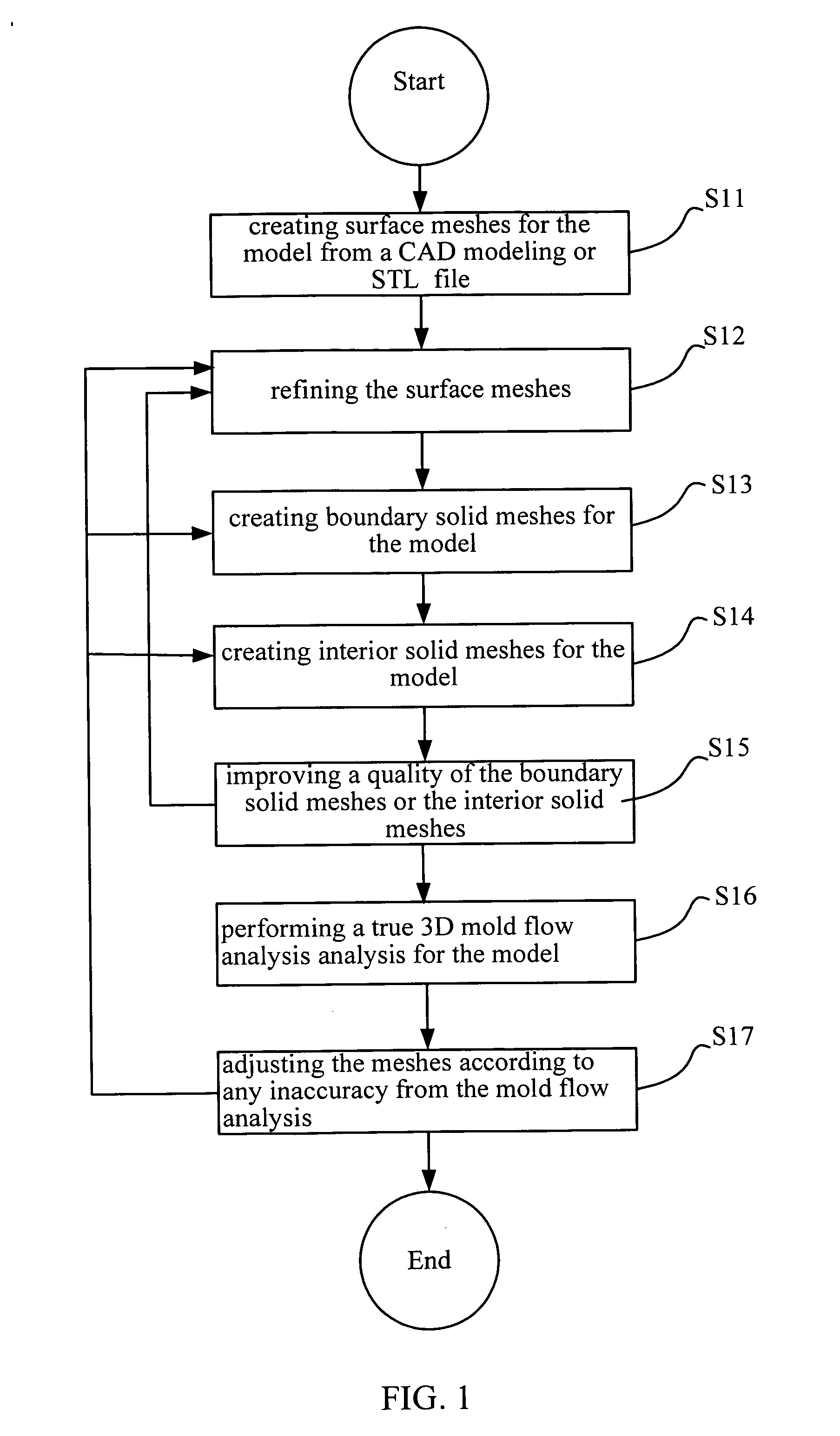
[0023] Please refer to FIG. 1. FIG. 1 is a flowchart of a method of the present invention. As shown in FIG. 1, the method of the present invention comprises steps S11, S12, S13, S14, S15, S16 and S17, and these steps are all automatically performed.

[0024] A shown in FIG. 1, in step S11 of the method of the present invention, a plurality of surface meshes are created from the surfaces of the geometry model. The geometry model can be obtained from CAD or a stereolithography (STL) file. The technology related to creating surface meshes by way of CAD models or stereolithography files is a very well-known technology, and so requires no further description.

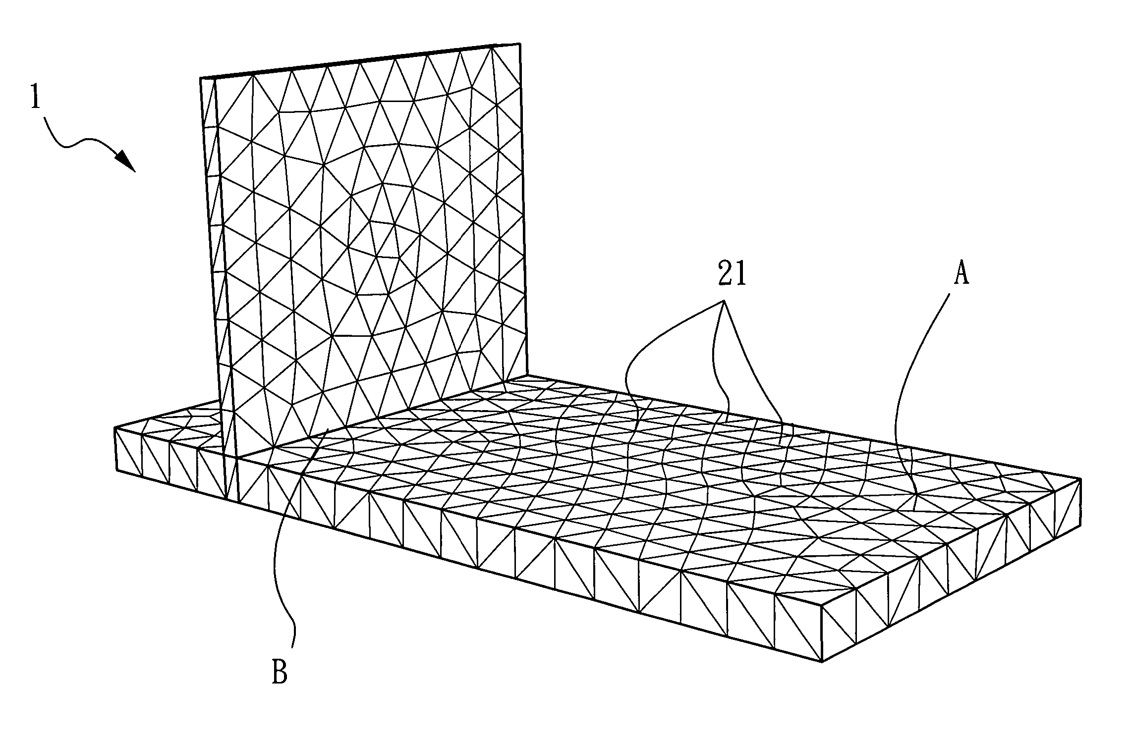
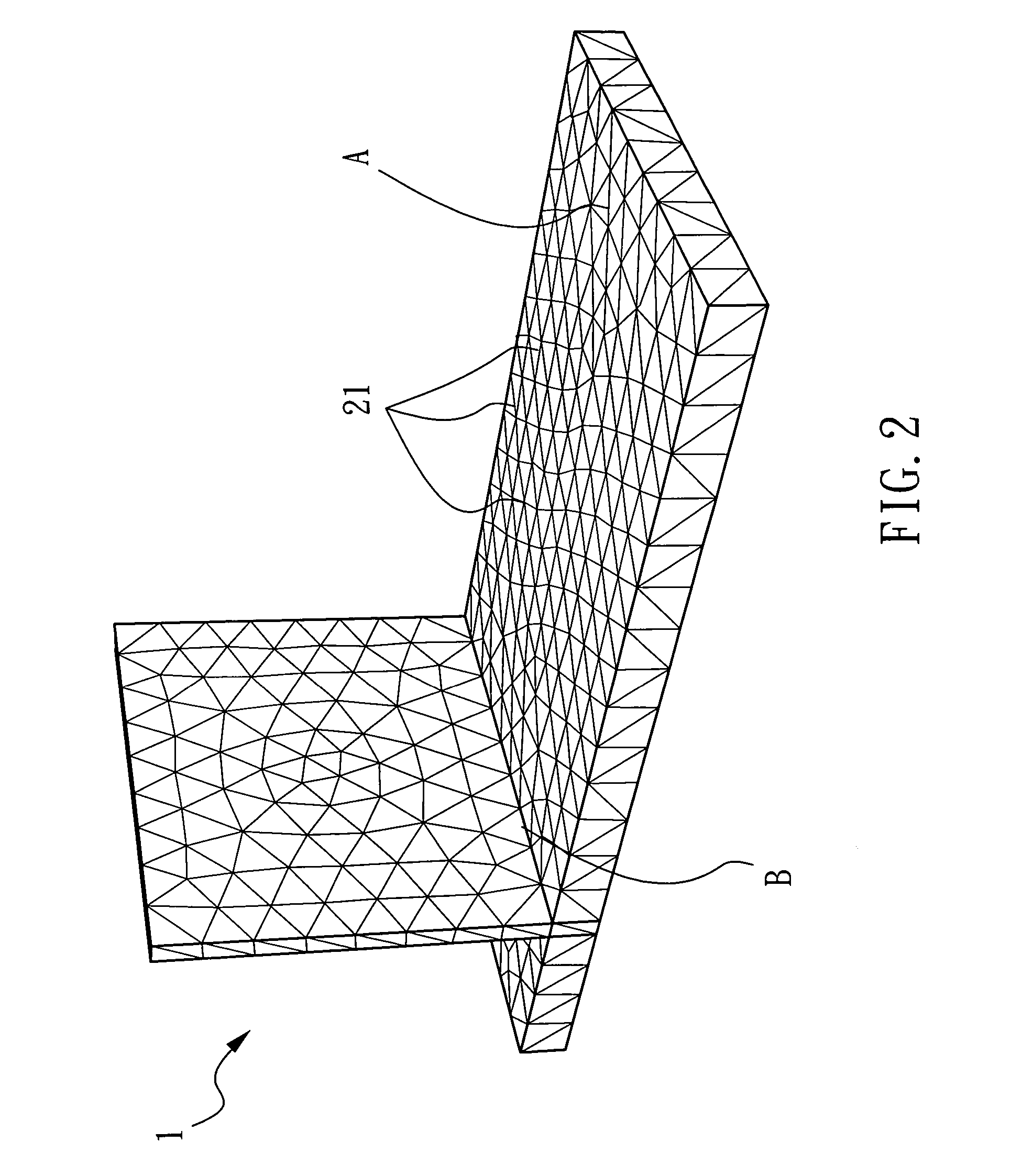
[0025] As shown in FIG. 2, in step S11, the plurality of surface meshes 21 are generated on the surface of the model 1...


PUM

PropertyMeasurementUnit
Thicknessaaaaaaaaaa

Abstract

An automated mesh creation method for automatically creating meshes for a model that may be applied in a mold flow analysis. The method includes the steps of creating surface meshes for the model from a CAD model or a STL file; refining the surface meshes; creating boundary solid meshes for the model; creating interior solid meshes for the model; improving the quality of the boundary solid meshes or the interior solid meshes; performing a true 3D model flow analysis for the model according to the surface meshes, the boundary solid meshes and the interior solid meshes; and adjusting the surface meshes, the boundary solid meshes or the interior solid meshes according to any inaccuracy of the mold flow analysis.

Description

BACKGROUND OF THE INVENTION [0001] 1. Field of the Invention [0002] The present invention relates to a mesh creation method, and, more particularly, to an automated mesh creation method for injection molding flow simulation application. [0003] 2. Description of the Related Art [0004] Generally, most CAE (Computer Aided Engineering) softwares are based on the application of various numerical analyses methods such as FDM, FEM, FVM and FBM, where a mesh, i.e., the numerical discretization of the analysis spatial domain is an essential step for the numerical simulation. The meshing procedure is performed on the simulated model before running the CAE analysis. Consequently, the quality of the mesh created directly affects the accuracy and efficiency of the numerical simulation, which subsequently affects the interpretation of these analysis results and the predictive capability of the CAE software. [0005] In the three-dimensional engineering application, three dimensional solid elements ...

Claims


Application Information

Patent Timeline
IPC IPC(8): G06T17/00
CPCB29C45/7693G06T17/20
Inventor CHIEN, CHING-CHANGLIU, CHENG-YUNGHSU, CHIA-HSIANG
Owner CORETECH SYST
Why Eureka
Try Eureka