Tank unit, ink jet recording head and method of manufacturing tank unit and ink jet recording head

a technology tank unit, which is applied in the field of ink jet recording head, can solve the problems of inability to meet the needs of washing water, inability to accurately record ink, and difficulty in exerting washing water washing pressure, etc., and achieves the effect of simple and attained, low cost, and simple and attained

Inactive Publication Date: 2007-05-03
CANON KK
View PDF17 Cites 4 Cited by
  • Summary
  • Abstract
  • Description
  • Claims
  • Application Information

AI Technical Summary

Benefits of technology

[0009] The method described so far is a rational method as a means for surely forming an airtight ink flow path in a short period of time at a low cost. In the prior art described above, however, the burrs melted out of the welding rib 1227 by the oscillations of the ultrasonic waves bulge over the ink flow path 1224 from the burr reservoir 12218, with the result that fine resinous grains are fragmented into pieces of dusts and clog in the ink discharge port 1337 of the recording element substrate 1330. This results in a discharge defect of the ink and might cause a decline of reliability on the ink jet recording head 1020.
[0010] For eliminating the dusts produced by the resin burrs, the ink flow path 1224 is washed in a subsequent washing step. The burr reservoir 1218 is not, however, all filled with the welded burrs, and a slight gap is left and becomes a stagnated portion when flowing the wash water. Then, a washing pressure of the wash water is hard to be exerted, and a considerably long period of time is required for completely flowing the dusts away. This makes it impossible to reduce assembly time and is a factor for raising the costs.
[0012] On the other hand, Japanese Patent Application Laid-Open Publication No. 8-183182 and U.S. Pat. No. 5,808,641 disclose technologies, wherein a resinous top board having a plurality of discharge ports and a plurality of liquid flow paths and a substrate for generating discharge energy, are integrally welded by irradiation of the laser beams. These technologies prevent such inconvenience that liquid discharge performance is declined by a distortion caused on the resinous top board and by resultant deformations of the liquid flow paths and the discharge ports as happened in the conventional method for making the resinous top board and the substrate integral by pressing the resinous top board against the substrate through an elastic member.
[0014] It is an object of the present invention to provide an ink jet recording head, wherein a connection between a tank holder (which will hereinafter also be called a “container holding member) for forming an ink flow path (which will hereinafter referred to also as a “liquid flow path”) and a flow path forming member, is conducted surely in a small number of steps at a short interval between flow paths without producing foreign matters within the ink flow path.
[0017] At least one surface of the junction surfaces in the periphery of the portions formed with the liquid flow paths of the container holding member and of the flow path forming member, is formed in the protruded shape from the non-junction surfaces. The flow path forming member is composed of the transparent resin having the transmissivity of the laser beam. The non-transmissive material having no transmissivity of the laser beam exists in at least the junction surface area of the container holding member. In the state where the flow path forming member is press-connected to the container holding member, the junction surface is welded by irradiating the periphery of the liquid flow path with the laser beam from the side of the flow path forming member, thereby forming the liquid flow path. The method, which is simple and attained at a low cost, provides the ink jet recording head capable of designing a high-density layout of the liquid flow paths with neither occurrence of the dusts of the resinous materials composing the container holding member and the flow path forming member nor formation of the stagnated portion within the liquid flow path.
[0018] As described above, the present invention yields an effect that the method, which is simple and attained at the low cost, enables the formation of the ink jet recording head capable of designing the high-density layout of the liquid flow paths with neither the occurrence of the dusts of the resinous materials composing the container holding member and the flow path forming member nor formation of the stagnated portion within the ink flow path.

Problems solved by technology

This results in a discharge defect of the ink and might cause a decline of reliability on the ink jet recording head 1020.
Then, a washing pressure of the wash water is hard to be exerted, and a considerably long period of time is required for completely flowing the dusts away.
This makes it impossible to reduce assembly time and is a factor for raising the costs.
As a result, there arises such inconvenience that the ink flow paths can not be disposed at a high density, and hence it is difficult to downsize the ink jet recording head.
These technologies prevent such inconvenience that liquid discharge performance is declined by a distortion caused on the resinous top board and by resultant deformations of the liquid flow paths and the discharge ports as happened in the conventional method for making the resinous top board and the substrate integral by pressing the resinous top board against the substrate through an elastic member.

Method used


Image

  • Tank unit, ink jet recording head and method of manufacturing tank unit and ink jet recording head
  • Tank unit, ink jet recording head and method of manufacturing tank unit and ink jet recording head
  • Tank unit, ink jet recording head and method of manufacturing tank unit and ink jet recording head

Examples


first embodiment

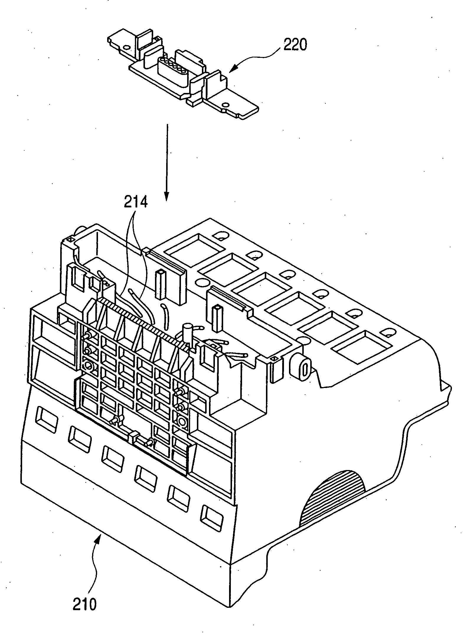
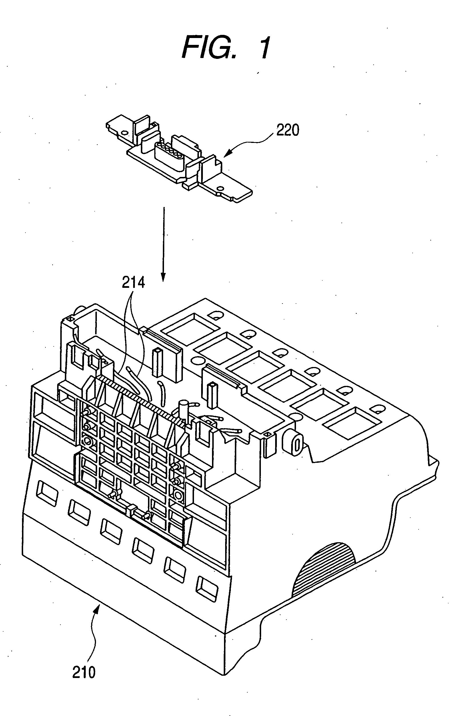
[0040] The discussion will start with explaining a construction of the ink jet recording head in the present invention and a relationship between related pieces of components such as a recording head cartridge, ink tanks, an ink jet recording apparatus body and a carriage. FIGS. 5 through 9 are explanatory views therefor. FIGS. 5A and 5B are perspective views of the recording head cartridge. FIG. 5A shows an assembled state. FIG. 5B shows a state where the ink tanks are removed. FIG. 6 is a perspective view of a tank holder unit and a recording element unit of the ink jet recording head. FIG. 7 is a schematic exploded perspective view of the ink jet recording head. FIG. 8 is a schematic partially cut perspective view of a recording element substrate constituting the recording element unit. FIG. 9 is a schematic perspective view showing a relationship between the ink jet recording head and the ink tanks. Configurations of the respective portions will hereinafter be explained with ref...

second embodiment

[0069] (Second Embodiment of the Present Invention)

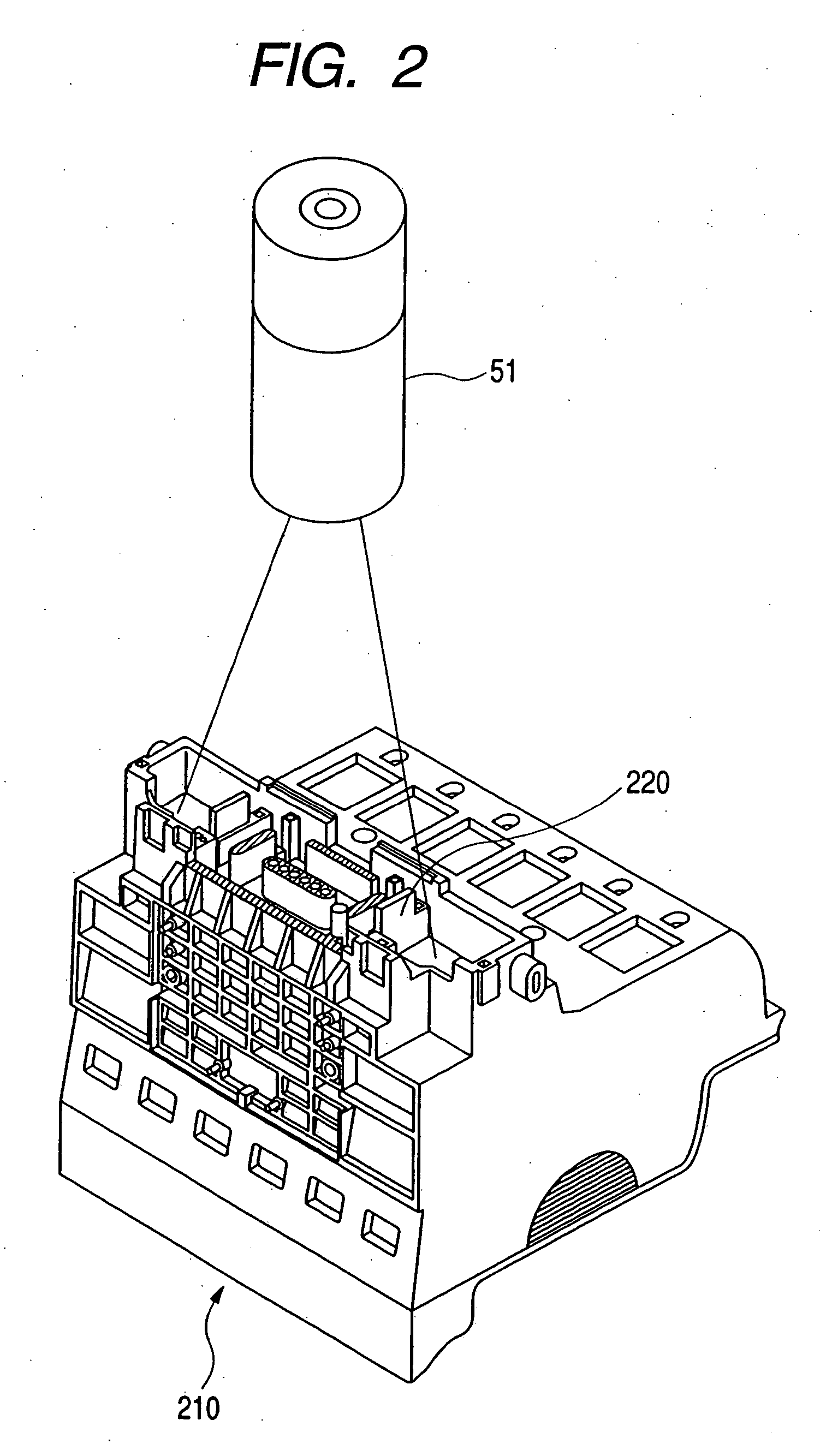
[0070] Next, a construction and features of the ink jet recording head according to a second embodiment of the present invention will be explained with reference to FIGS. 11A, 11B and 11C. FIGS. 11A, 11B and 11C are schematic side surface partial sectional views showing a step of connecting the flow path forming member to the tank holder of the ink jet recording head in the second embodiment of the present invention. FIG. 11A shows a relative relationship between the tank holder and the flow path forming member before the connection. FIG. 11B shows a state in which the flow path forming member is irradiated with the laser beam in a way that abuts the flow path forming member on the tank holder. FIG. 11C shows a connected state. The same members as those in the first embodiment are marked with the same reference numerals.

[0071] In FIGS. 11A to 11C, the materials composing the flow path forming member 220 and the tank holder 211 are ...

third embodiment

[0075] (Third Embodiment of the Present Invention)

[0076] Next, a construction and features of the ink jet recording head according to a third embodiment of the present invention will be explained with reference to FIGS. 12A, 12B and 12C. FIGS. 12A, 12B and 12C are schematic side surface partial sectional views showing a step of connecting the flow path forming member to the tank holder of the ink jet recording head in the third embodiment of the present invention. FIG. 12A shows a relative relationship between the tank holder and the flow path forming member before the connection. FIG. 12B shows a state in which the flow path forming member is irradiated with the laser beam in a way that abuts the flow path forming member on the tank holder. FIG. 12C shows a connected state. The same members as those in the first embodiment are marked with the same reference numerals.

[0077] In FIG. 12, the materials composing a flow path forming member 221 and a tank holder 212 are the same as thos...


PUM

PropertyMeasurementUnit
diameteraaaaaaaaaa
diameteraaaaaaaaaa
diameteraaaaaaaaaa

Abstract

A flow path forming member is formed with a recessed portion for forming an ink flow path. A junction surface of the flow path forming member is in a protruded state from a non-junction surface. The flow path forming member is composed of a transparent resin exhibiting transmissivity of laser beam. A tank holder is composed of a non-transmissive resin having no transmissivity of the laser beam. In a state where the flow path forming member is press-connected to the tank holder, the junction surface is welded by irradiating a periphery of the ink flow path with the laser beam from the side of the flow path forming member, thereby forming an ink flow path. Provided is an ink jet recording head in which the tank holder and the flow path forming member that serve to form the ink flow path are surely connected by a small number of steps without producing foreign matters within the ink flow path.

Description

BACKGROUND OF THE INVENTION [0001] 1. Field of the Invention [0002] The present invent relates to an ink jet recording head of an ink jet recording apparatus that performs recording by discharging inks. [0003] 2. Description of the Related Art [0004]FIG. 17 shows an exploded perspective view for explaining a construction of a conventional ink jet recording head. FIG. 18 shows a cross sectional view of a recording head cartridge in which an ink tank is installed in the ink jet recording head. FIGS. 19A through 19C show schematic sectional enlarged views for explaining a step of forming an ink flow path. [0005] An ink jet recording head 1020 shown in FIGS. 17 and 18 has hitherto used a method of assembling a tank holder unit 1200 by ultrasonic-wave-welding an flow path forming member 1220 to a tank holder 1210 in. order to form an ink flow path 1214 for guiding an ink in an ink tank 1040 to a recording element unit 1300 via the tank holder 1201. [0006] As shown in FIG. 18, in a state ...

Claims


Application Information

Patent Timeline
Patent Type & Authority Applications(United States)
IPC IPC(8): B41J2/175
CPCB41J2/175Y10T29/49401B41J2/17523B41J2/1753B29L2031/767B29C65/08B29C65/1635B29C65/1664B29C65/1677B29C65/1683B29C65/8253B29C66/112B29C66/114B29C66/1142B29C66/3022B29C66/30223B29C66/322B29C66/54B29C66/542B29C66/543B29C66/545B29C66/73162B29C66/81267B41J2/1752B29C66/8322B29C66/02B29C66/30322B29C66/73921B29C66/71B29K2071/12
Inventor MORITA, OSAMU
Owner CANON KK
Why Eureka
Try Eureka