Image-based printer system monitoring

Active Publication Date: 2007-05-03
RICOH KK
View PDF9 Cites 14 Cited by
  • Summary
  • Abstract
  • Description
  • Claims
  • Application Information

AI Technical Summary

Benefits of technology

[0006] The present invention comprises a machine monitoring interface (e.g., a printer monitoring interface) that uses a combination of dynamic three dimensional representations of a machine and actual photographic images (still or video) to give an operator monitoring the machine realtime feedback, in both graphical and actual-image form, of areas of the machine experiencing problems. The graphical images provide the operator with a representation of the overall system, and the actual images provide the operator with the ability to actually see the problem that is occurring. The graphical and actual-image views are combined so that the operator can quickly and easily identify where in the system the problem is occurring, and quickly diagnose problems and determine solutions.
[0007] In a preferred embodiment, a three-dimensional graphics engine and dedicated graphics acceleration hardw

Problems solved by technology

The ability to instantly communicate the status of a printer to a user is limited by the text-based and two-dimensional graphical user interfaces used for communicating the printer status in the prior art.
Problems are depicted in text format or diagram drawings; such depictions provide a generic representation of a problem and do not fully communicate the actual state of the printer.
This makes it very difficult to det

Method used


Image

  • Image-based printer system monitoring
  • Image-based printer system monitoring
  • Image-based printer system monitoring

Examples


Embodiment Construction

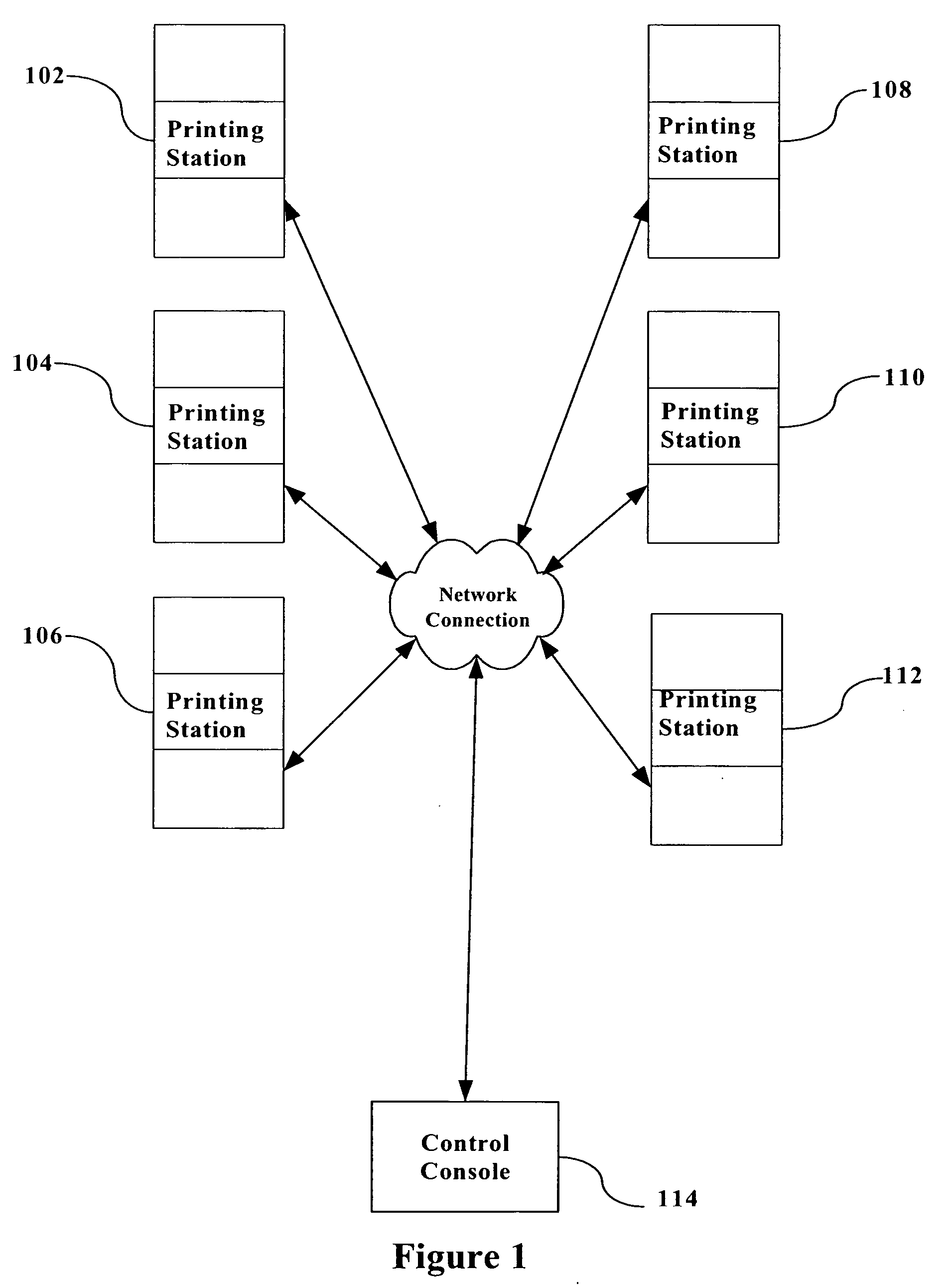
[0012]FIG. 1 is a block diagram illustrating a typical multi-station printing system. Multiple printing stations 102, 104, 106, 108, 110, and 112 are coupled via a network connection to a control console 114. The network connection can be hardwired, over an internal network, or the internet, for example.

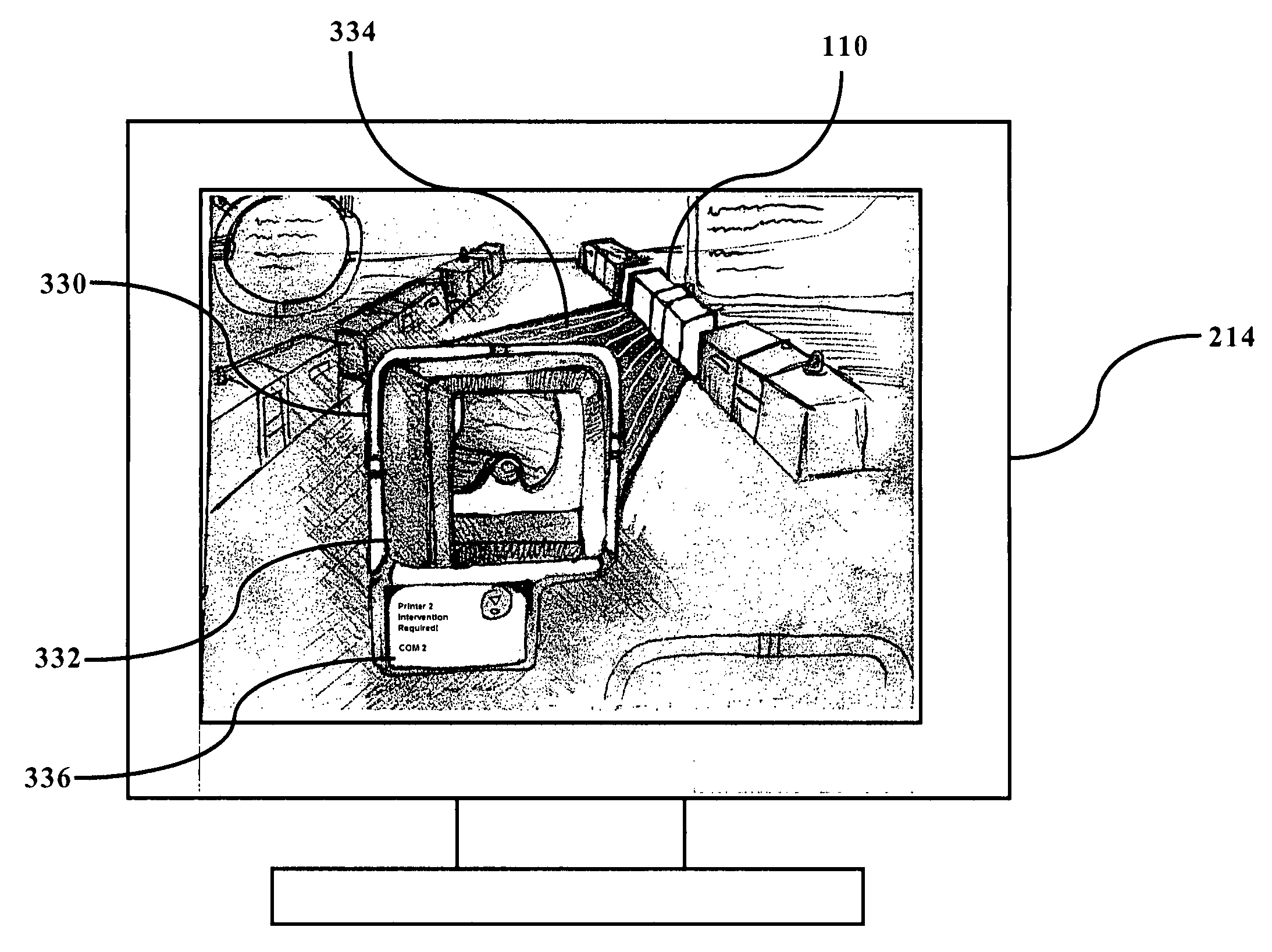
[0013] The printing stations illustrated in FIG. 1 can be any type of printing station, for example, a 3900 Duplex Advanced Function printing system manufactured by IBM. The IBM 3900 is a complex system and is thus perfectly suited for use with the present invention. Other examples of printing systems that would benefit from the use of the present invention include small and medium-scale printers that may require operator intervention when some mechanism in the printing process fails, as well as personal-use printers. Because users must often refer to the technical manual or documentation to locate a problem and identify a process to correct the problem, the present invention, which...


PUM


Abstract

A printer monitoring interface is disclosed that uses a combination of dynamic three dimensional representations of a printing system and actual photographic images (still or video) of problem areas to give an operator monitoring the printing system realtime feedback, in both graphical and actual-image form, of areas of the printing system experiencing problems. The graphical images (which may also be actual photographic images) provide the operator with a representation of the overall system, and the actual images of problem areas provide the operator with the ability to actually see the problem that is occurring. The graphical and actual-image views are combined so that the operator can quickly and easily identify where in the system the problem is occurring, and quickly diagnose problems and determine solutions.

Description

BACKGROUND OF THE INVENTION [0001] 1. Field of the Invention [0002] This invention relates to the monitoring of printing systems and, more particularly, to a system for providing realtime status information for a printing system. [0003] 2. Description of the Related Art [0004] The ability to instantly communicate the status of a printer to a user is limited by the text-based and two-dimensional graphical user interfaces used for communicating the printer status in the prior art. Problems are depicted in text format or diagram drawings; such depictions provide a generic representation of a problem and do not fully communicate the actual state of the printer. For example, if a paper jam occurs in the printing system, the printer operator must often reference a diagram displayed on a small screen that displays an iconic representation of the problem area without giving anything other than a general indication where in the printing system the particular area is located. This makes it ve...

Claims


Application Information

Patent Timeline
IPC IPC(8): G06F3/12
CPCG03G15/55G06F3/121G06F3/1229G03G15/5075G03G15/502G03G2215/00109G06F3/1285G03G15/00
Inventor MATHEWSON, EDWARD
Owner RICOH KK
Why Eureka
Try Eureka