
Luminance nonuniformity adjustment method and luminance nonuniformity adjustment module using this method

a technology of non-uniformity and adjustment method, applied in the field of luminance non-uniformity adjustment method and luminance non-uniformity adjustment module, can solve problems such as improper coloring and improper coloring, and achieve the effect of inhibiting correction errors

Inactive Publication Date: 2007-05-03
NORITZ CORP
View PDF1 Cites 7 Cited by
  • Summary
  • Abstract
  • Description
  • Claims
  • Application Information

AI Technical Summary

Benefits of technology

[0005] The present invention overcomes the problems and short comings in the related art and it is an object thereof to provide a technology in the field of luminance nonuniformity adjustment which inhibits correction error due to improper coloring through a simple method.
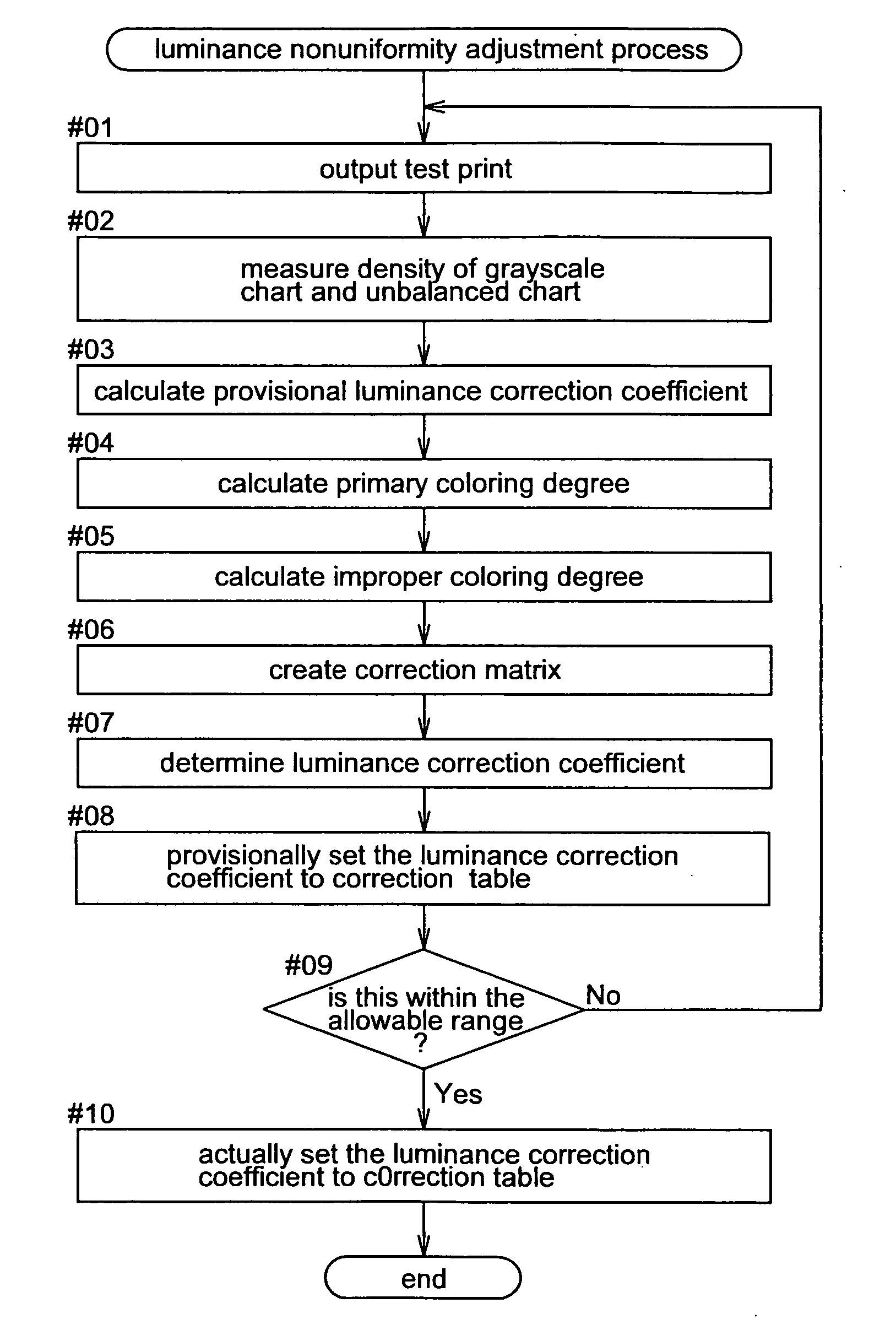
[0006] In accordance with an embodiment of the present invention, a luminance nonuniformity adjustment method stores, on a correction table, a luminance correction coefficient for each optical element determined through a test print using a light-sensitive material. This eliminates the luminance nonuniformities in the optical elements of a color laser print head that controls a plurality of optical elements in a linear array for each color of the three basic colors, according to exposure gradation values based on image data, to expose the light-sensitive material. The present method comprises calculating a provisional luminance correction coefficient by comparing a measured density value for a grayscale chart of areas having different density values and a predetermined target density value. An improper coloring degree, which is the degree of improper coloring that occurs when other colors are expressed when developing a specific color is calculated from the measured density values for the grayscale chart and an unbalanced chart where the gray balance has been altered. The provisional luminance correction coefficient is the corrected using the calculated improper coloring degree to determine a final luminance correction coefficient.
[0007] In the present method, the measured density values corresponding to the grayscale chart and the unbalanced chart where the gray balance has been altered (for example, this is generated by changing only the B: blue gradation value from gray) to calculate the improper coloring degree. The improper, coloring degree is the degree of unintentional production of a color other than a specific color (such as G: green or R: red) when only the specific color (for example, B: blue) has been changed. The provisional luminance correction coefficients that have been calculated through conventional luminance nonuniformity adjustment is then corrected, which does not consider improper coloring. The luminance correction coefficients, which are ultimately obtained, inhibit the negative effects due to improper coloring, thereby achieving luminance nonuniformity adjustment of is high precision.
[0010] Since the equation uses a simple matrix calculation, the final luminance correction coefficients can be determined using the calculated improper coloring degrees to correct the provisional luminance correction coefficients without the burden of heavy computation.
[0013] It is appreciated that the luminance nonuniformity adjustment module can adopt the configurations for practicing the implementations as aforesaid and can similarly attain all of the effects of the luminance nonuniformity adjustment method described herein.

Problems solved by technology

An improper coloring degree, which is the degree of improper coloring that occurs when other colors are expressed when developing a specific color is calculated from the measured density values for the grayscale chart and an unbalanced chart where the gray balance has been altered.

Method used


Image

  • Luminance nonuniformity adjustment method and luminance nonuniformity adjustment module using this method
  • Luminance nonuniformity adjustment method and luminance nonuniformity adjustment module using this method
  • Luminance nonuniformity adjustment method and luminance nonuniformity adjustment module using this method

Examples


Embodiment Construction

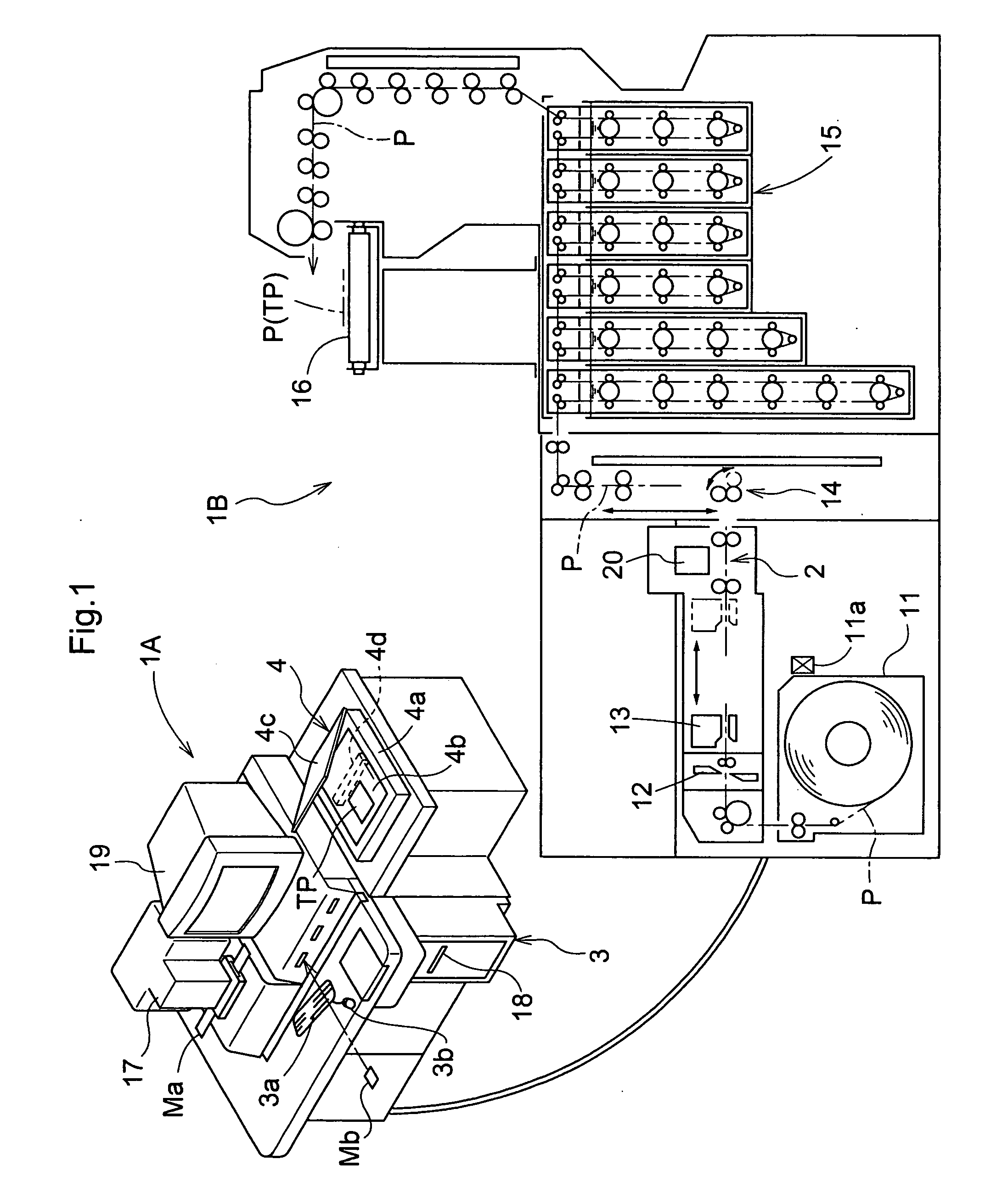
[0024]FIG. 1 shows a digital laser printer serving as an image forming device, which incorporates the luminance nonuniformity adjustment module in accordance with an embodiment of the present invention. The digital laser printer is also called a digital minilab. The digital laser printer comprises a print station 1B that exposes and develops print paper P, e.g., a light-sensitive material and an operation station 1A that performs appropriate image processing on the captured image data, which have been obtained from image recording media such as developed photographic film Ma or a digital camera memory card Mb and then transfers these to the print station 1B.

[0025] The print station 1B draws out roll-type print paper P that is stored in a print paper magazine 11, cuts the print paper P to the print size with a short cutter 12 and transports the cut print paper P horizontally with a paper-sandwiching type horizontal carrying mechanism 13 to an exposure unit 2. The horizontal carrying...


PUM


Abstract

A luminance nonuniformity adjustment module for eliminating luminance nonuniformities in light emitting elements determines a luminance correction coefficient for each light-emitting element through a test print. The luminance nonuniformity adjustment module comprises a provisional luminance correction coefficient calculation unit, an improper coloring degree calculation unit and a luminance correction coefficient determination unit. The provisional luminance correction coefficient calculation unit calculates a provisional luminance correction coefficient by comparing a measured density value for a grayscale chart and a predetermined target density value. The improper coloring degree calculation unit calculates an improper coloring degree, which is the degree of improper coloring that occurs when other colors are expressed when developing a specific color, from the measured density values for the grayscale chart and an unbalanced chart in which the gray balance has been altered. The luminance correction coefficient determination unit corrects the provisional luminance correction coefficient using the improper coloring degree.

Description

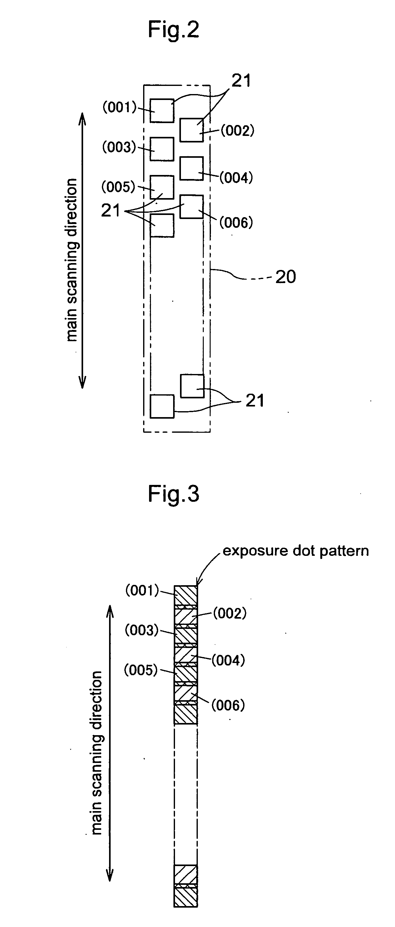
FIELD OF THE INVENTION [0001] The present invention relates to luminance nonuniformity adjustment methods, and luminance nonuniformity adjustment modules using the same, which store on a correction table a luminance correction coefficient for each light-emitting element that has been found through a test print that uses a light-sensitive material, in order to eliminate luminance nonuniformities in the optical elements of a color laser print head that controls a plurality of light-emitting elements lined up in a linear array for each color of the three basic colors in accordance with the exposure gradation values based on the image data in order to expose the light-sensitive material. DESCRIPTION OF THE RELATED ART [0002] Digital laser printers that send drive signals based on image data to fluorescent light-emitting elements, which are employed as optical elements, lined up in a linear array to cause them to radiate light and by sensitizing a light-sensitive material to form images ...

Claims


Application Information

Patent Timeline
Patent Type & Authority Applications(United States)
IPC IPC(8): H04N1/46
CPCH04N1/4015H04N1/6033
Inventor GOMA, TATSUJINAKATANI, YOSHIYUKINISHIHARA, TAKESHI
Owner NORITZ CORP
Learn More