
A method of calibrating an ultrasonic scanner

An ultrasonic and scanning line technology, applied in the field of calibrating ultrasonic scanners with transducers, can solve the problems of different calibration methods, time-consuming and labor-intensive ultrasonic scanners, etc., and achieve the effect of avoiding calibration errors

Active Publication Date: 2021-07-30
VERATHON +4
View PDF2 Cites 0 Cited by
  • Summary
  • Abstract
  • Description
  • Claims
  • Application Information

AI Technical Summary

Problems solved by technology

[0007] To sum up, the calibration of ultrasonic scanners is time-consuming and labor-intensive, and different calibration methods will be produced due to different calibration personnel or environments.

Method used


Image

  • A method of calibrating an ultrasonic scanner
  • A method of calibrating an ultrasonic scanner
  • A method of calibrating an ultrasonic scanner

Examples


Embodiment Construction

[0060] This patent application is intended to describe one or more embodiments of the invention. However, it should be understood that absolute values ​​used in this patent, such as "must", "will" and the like, as well as specific quantities, will be interpreted to apply to one or more specific embodiments, but not all embodiments. Therefore, the embodiments of the present invention may omit or include various modifications, and one or more features or aspects are described before and after these absolute terms.

[0061] Embodiments of the present invention can be used in numerous general purpose or special purpose computer system environments or configurations today. Well-known computer systems, environments, and / or configurations may be suitable for use with the present invention, but are not limited to, electronic medical equipment, personal computers, server computers, hand-held or laptop devices, multi-function processing server systems, microprocessor-based systems, set...


PUM


Abstract

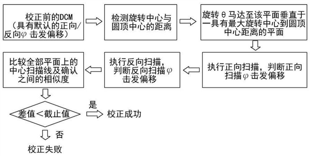
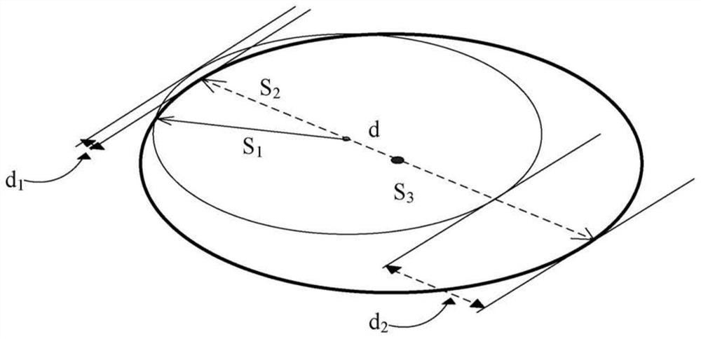
The invention discloses a method for calibrating an ultrasonic scanner. Through the rotation axis and the θ axis perpendicular to the axis, it includes: rotating a transducer along the axis and collecting the first energy from the target reflection surface on the scanning plane. data; calculate the angle of the first maximum peak intensity from the first data; rotate the transducer 180° along the θ axis; rotate the transducer along the axis and collect second data from the same target reflective surface on the same scan plane; calculating the angle of the second maximum peak intensity according to the second data; and subtracting the angles of the two maximum peak intensities to obtain a difference. The present invention can calibrate the ultrasonic scanner according to the difference, which can not only omit the existing calibration method of using a water tank or an additional ultrasonic target, but also avoid calibration errors caused by parallax.

Description

[0001] priority claim [0002] This patent application claims priority to US Application Serial No. 61 / 936,232, filed February 5, 2014, which is incorporated herein by reference. technical field [0003] The present invention relates to a method of calibrating an ultrasonic scanner, and in particular to a method of calibrating an ultrasonic scanner with a transducer. Background technique [0004] Existing ultrasonic scanners with transducers can be used to measure bladder volume. However, due to errors in calibration before measurement, the measured bladder volume is quite different from the actual situation. [0005] The existing calibration method uses a spiral ultrasonic target to be placed in a water tank for manual calibration, and after the calibration is completed, the water in the water tank is emptied for subsequent measurement, which is very time-consuming and labor-intensive. Furthermore, the calibration process assumes that the center of the dome is perfectly a...

Claims


Application Information

Patent Timeline
Patent Type & Authority Patents(China)
IPC IPC(8): A61B8/00A61B8/08
CPCA61B8/4466A61B8/4483A61B8/483A61B8/58A61B8/5207A61B8/5269A61B8/56
Inventor 罗思崔俊焕史蒂芬·杜迪哈亚当·斯科特·加里森克雷格·E·纳尔逊劳伦斯·尼尔·胡恩莫瑞斯·邓恩马修·卡佩罗安德鲁·亚姆
Owner VERATHON
Learn More