Adaptive cooling method for computer rack enclosure

a technology of adaptive cooling and computer rack, which is applied in the direction of liquid/fluent solid measurement, electric apparatus casing/cabinet/drawer, instruments, etc., can solve the problems of low pressure range, low cost of pressure transducers, and inability to accurately measure this low pressure range. , to achieve the effect of low cos

Active Publication Date: 2007-05-03
WRD CORP
View PDF37 Cites 61 Cited by
  • Summary
  • Abstract
  • Description
  • Claims
  • Application Information

AI Technical Summary

Benefits of technology

[0012] What is needed is a low cost and robust way to measure if the cooling system air flow is matched to the combined CFM of the individual computer's cooling fans. Thus if the compu

Problems solved by technology

The problem with using pressure transducers is that the observed pressure differential is typically very small, on the order of 0.1 inches of water (0.0036PSI), or less.
Pressure transducers that can accurately measure this low range of pressure are relatively expensive.
Additionally, any pressure transducer that is chosen has a minimum pressure sensing capability, below which the transducer will not work.
The lower the specified minimum is, the

Method used


Image

  • Adaptive cooling method for computer rack enclosure
  • Adaptive cooling method for computer rack enclosure
  • Adaptive cooling method for computer rack enclosure

Examples


Embodiment Construction

[0019] A description of preferred embodiments of the invention follows.

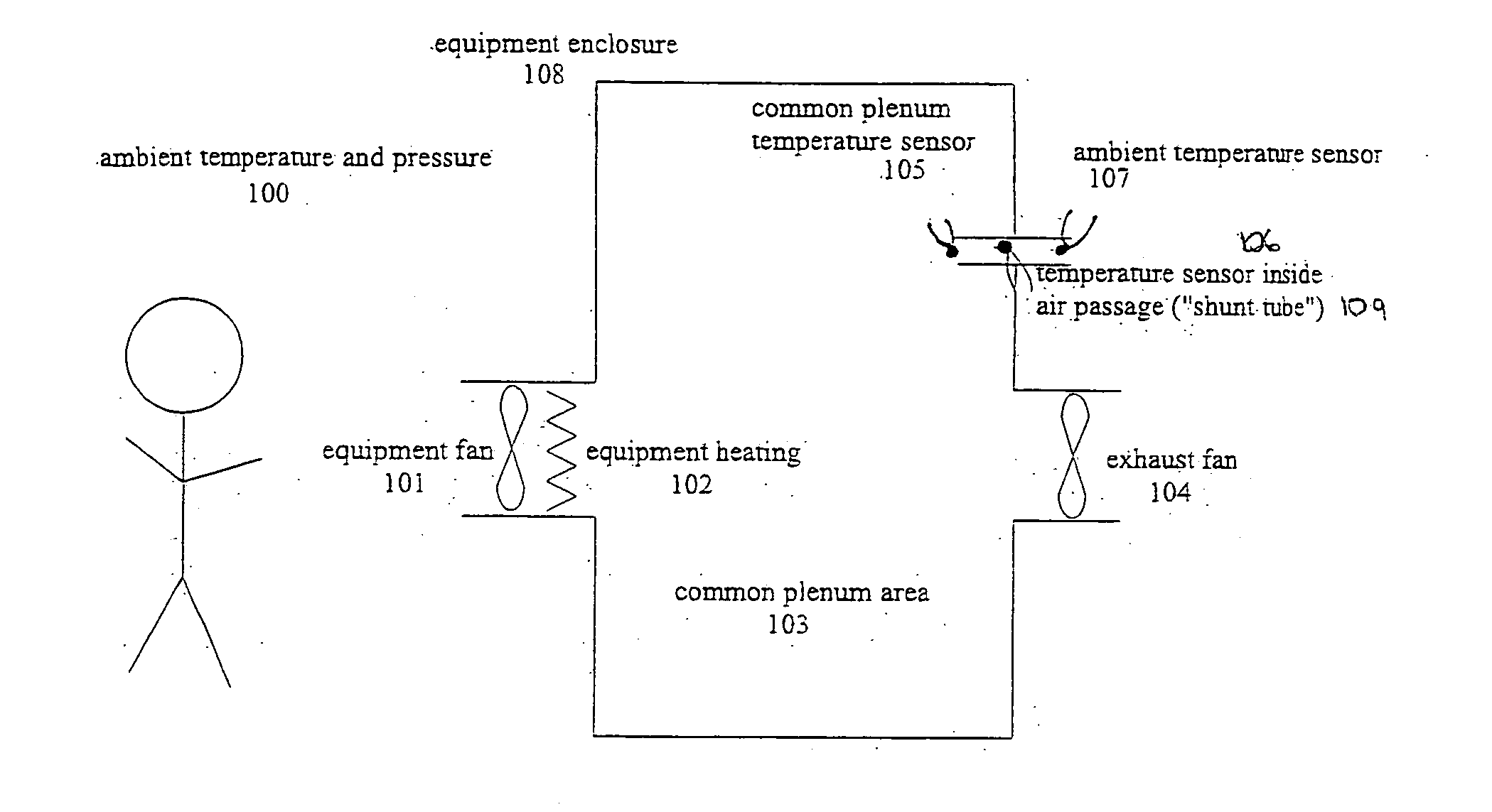
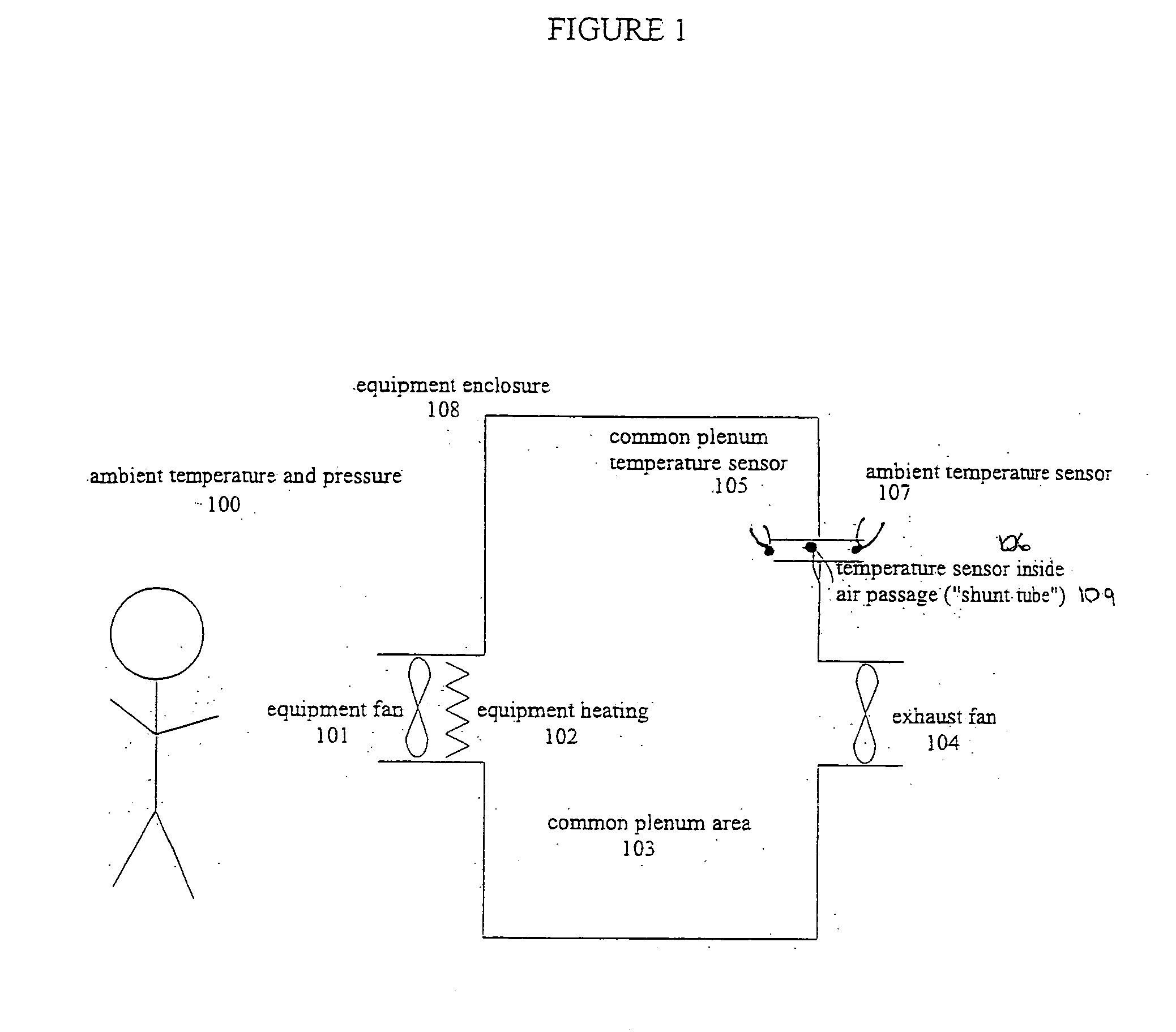
[0020] One basic CFM difference detection method according to the invention shown in FIG. 1. The technique involves an equipment rack or enclosure (108) that has at least one piece of equipment (such as a computer) with a fan (101) that blows air into a common plenum area (103). The equipment also generates heat (102) so that the air that goes into the common plenum area is heated above ambient temperature. The equipment enclosure also has an exhaust fan (104) that is meant to exhaust the heated air from the common plenum area, at the same CFM as is being introduced into the common plenum area, by the equipment fan (101). Temperature sensors include plenum sensor (105) for measuring the temperature of the air in the common area (103), ambient sensor (107), for measuring the temperature of the ambient room air (100), and sensor (106) for measuring the temperature of the air inside a small air passage (“shunt tube...


PUM


Abstract

A technique for cooling equipment racks that contain multiple individual devices, such as computers, that each have their own internal cooling fans. An air passage (“shunt tube”) is placed between a compartment inside the rack, and the ambient air outside the rack, or between compartments inside the rack. Sensors inside the air passage detect movement of the air inside the passage, and thus indirectly measure the presence of a differential pressure. The preferred sensor embodiment uses temperature sensors, and takes advantage of the differences of the air temperatures inside the computer rack, and outside the computer rack (or between internal computer rack compartments) to determine if the air is moving through the air passage, and which direction the air is moving. In response to the measurements, a control system is configured to drive the plenum to a slight vacuum, and then slowly reduce an exhaust fan until the plenum is slightly pressurized, at which point the fan speeds up and again creates a slight vacuum. This allows the rack enclosure to continuously adapt to any changes in cooling requirements, as the computer utilization changes.

Description

RELATED APPLICATION(S) [0001] This application claims the benefit of U.S. Provisional Application No. 60 / 705,793, filed on Aug. 5, 2005. The entire teachings of the above application(s) are incorporated herein by reference.BACKGROUND OF THE INVENTION [0002] It has been estimated that in most of today's data centers, electronic equipment racks generate between 5 to 12 KiloWatts (KW) of heat. The newest computers (servers) being used in data centers are smaller and more powerful, and allow for a very dense placement of machines inside an equipment rack enclosure. Some estimates are that future heat loads inside equipment racks could go beyond 20 KW. The cooling systems used in these equipment racks are clearly important to the reliability of these data centers. [0003] Efficiency is one of the most important aspects of a rack cooling system. The high cost of air conditioning precludes simply making and distributing more cold air than is needed for cooling. The most efficient system wil...

Claims


Application Information

Patent Timeline
IPC IPC(8): H05K7/20
CPCG06F1/206H05K7/20145H05K7/20209H05K7/20572H05K7/207H05K7/20745H05K7/20836
Inventor JOHNSON, DOUGLAS A.BOYD, STEPHEN B.
Owner WRD CORP
Why Eureka
Try Eureka