
NxN multiple-input multiple-output transceiver

a transceiver and multiple input technology, applied in the field of nn multiple input multiple output (mimo) transceivers, can solve the problems of not being able to employ a structure in which one frequency synthesizer is used, and not being able to reduce the cost of the transceiver

Inactive Publication Date: 2007-05-03
SAMSUNG ELECTRONICS CO LTD
View PDF5 Cites 2 Cited by
  • Summary
  • Abstract
  • Description
  • Claims
  • Application Information

AI Technical Summary

Benefits of technology

[0013] According to an aspect of the present invention, there is provided an N×N MIMO transceiver which comprises a plurality of transceivers, each comprising at least one transceiver circuit; an oscillation unit which is configured to generate a differential signal which is supplied to the at least one transceiver circuit; a plurality of buffers, which are mounted in a bypass line between the at least one transceiver

Problems solved by technology

The early MIMO transceiver used a pair of connected transceivers, which has no way to reduce the cost of the transceiver.
However, such conventional methods and apparatuses can be designed to use one frequency synthesizer by applying a pair of receiver circuits and a pair of transmitter circuits to the MIMO transceiver of a 2×2 type, but the 4×4 to N×N MIMO transceivers, each having more than two pairs of receiver circuits and transmitter circuits, cannot employ a structure in which one frequency synthesizer is used.

Method used


Image

  • NxN multiple-input multiple-output transceiver
  • NxN multiple-input multiple-output transceiver
  • NxN multiple-input multiple-output transceiver

Examples


Embodiment Construction

[0037] Hereinafter, description will be made in detail of exemplary embodiments of the present invention with reference to the accompanying drawings.

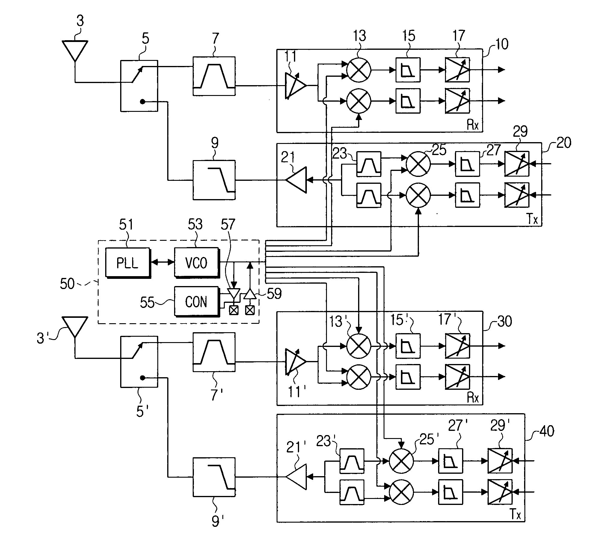
[0038]FIG. 1 is a circuit diagram for showing a 2×2 MIMO transceiver according to an exemplary embodiment of the present invention. As shown in FIG. 1, the 2×2 MIMO transceiver has a pair of antennas 3 and 3′, a pair of transceiver switches 5 and 5′, a pair of band pass filters 7 and 7′, a pair of low pass filters 9 and 9′, a pair of receiver circuits 10 and 30, a pair of transmitter circuits 20 and 40, and a frequency synthesizer 50.

[0039] Each antenna 3 or 3′ is shared by a respective pair of the transmitter and receiver circuits. For example, antenna 3 is shared by receiver circuit 10 and transmitter circuit 20. Each antenna 3 or 3′ thus receives and provides an RF signal to its corresponding receiver circuit 10 or 30, or transmits an RF signal output from its corresponding transmitter circuit 20 or 40 output The RF signal may be r...


PUM


Abstract

An N×N multiple-input multiple-output (MIMO) transceiver is provided. The transceiver includes a plurality of transceivers, each including at least one transceiver circuit; an oscillation unit which is configured to generate a differential signal which is supplied to the at least one transceiver circuit; a plurality of buffers, which are mounted in a bypass line between the at least one transceiver circuit and the oscillation unit and are configured to amplify and bypass the differential signal or input and amplify the differential signal; and a buffer control unit which is configured to control the plurality of buffers to bypass or input the differential signal.

Description

CROSS-REFERENCE TO RELATED APPLICATION [0001] This application claims priority from Korean Patent Application 10-2005-0104377, filed on Nov. 2, 2005, the entire contents of which are incorporated herein by reference. BACKGROUND OF THE INVENTION [0002] 1. Field of the Invention [0003] Apparatuses consistent with the present invention relate to an N×N multiple-input multiple-output (MIMO) transceiver, and more particularly, to an N×N MIMO transceiver capable of supplying a differential signal to plural transceivers by using one frequency synthesizer. [0004] 2. Description of the Related Art [0005] With the spread of high-speed Internet, digital home networks are built in combination with high-speed internet networks such as digital subscriber line (DSL) and wireless local area networks, and, as high-capacity audio-visual (AV) multimedia services such as high definition class (HD-class) broadcasts increase, wireless communication technologies are required which have stable and high thr...

Claims


Application Information

Patent Timeline
IPC IPC(8): H04L1/02
CPCH04B7/0413H04L1/06
Inventor JEON, SANG-YOONBANG, HEE-MUNJUNG, SUNG-JAELEE, HEUNG-BAE
Owner SAMSUNG ELECTRONICS CO LTD
Learn More