Tube for installing an optical fiber unit having a lubricous surface

a technology of lubricating surface and installation tube, which is applied in the direction of optics, fibre mechanical structures, instruments, etc., can solve the problems that the installation tube b>10/b> cannot be easily installed, and achieve the effect of convenient installation

Inactive Publication Date: 2007-05-03
LG CABLE LTD (KR)
View PDF6 Cites 56 Cited by
  • Summary
  • Abstract
  • Description
  • Claims
  • Application Information

AI Technical Summary

Benefits of technology

[0008] The present invention is designed to solve the problem of the prior art, and therefore an object of the invention is to provide a tube for gas pressure installation, which may be easily installed in a communication pipe.
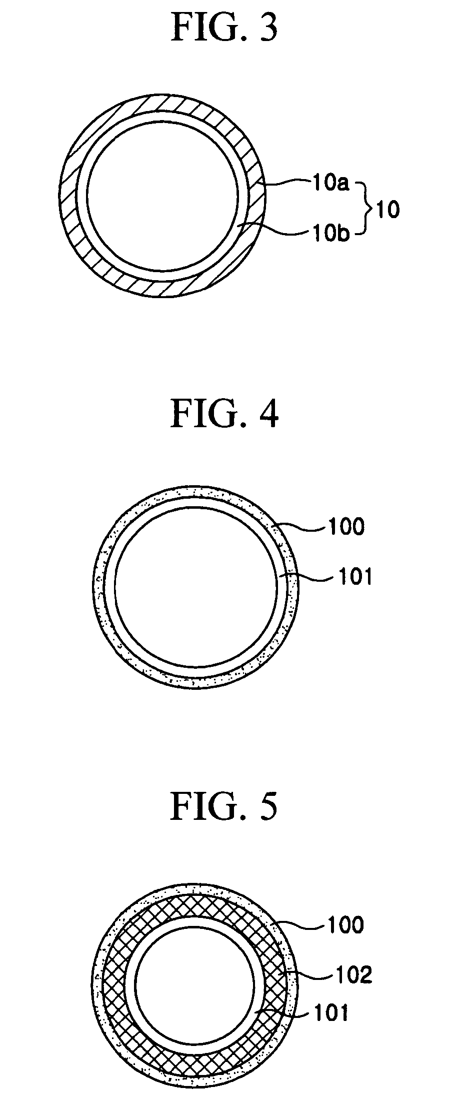
[0010] The tube preferably further includes a reinforcing layer interposed between the inner layer and the sheath so as to increase strength of the tube itself.
[0012] In another aspect of the invention, there is also provided a tube for installing an optical fiber unit, which is to be installed in a communication pipe, wherein the tube is made of a single layer made of polymer having a lower coefficient of friction than polyethylene so as to decrease friction against the optical fiber unit contacted with an inner circumference of the tube while the optical fiber unit is installed by gas pressure as well as friction generated on an outer circumference of the tube while the tube is installed in the communication pipe.

Problems solved by technology

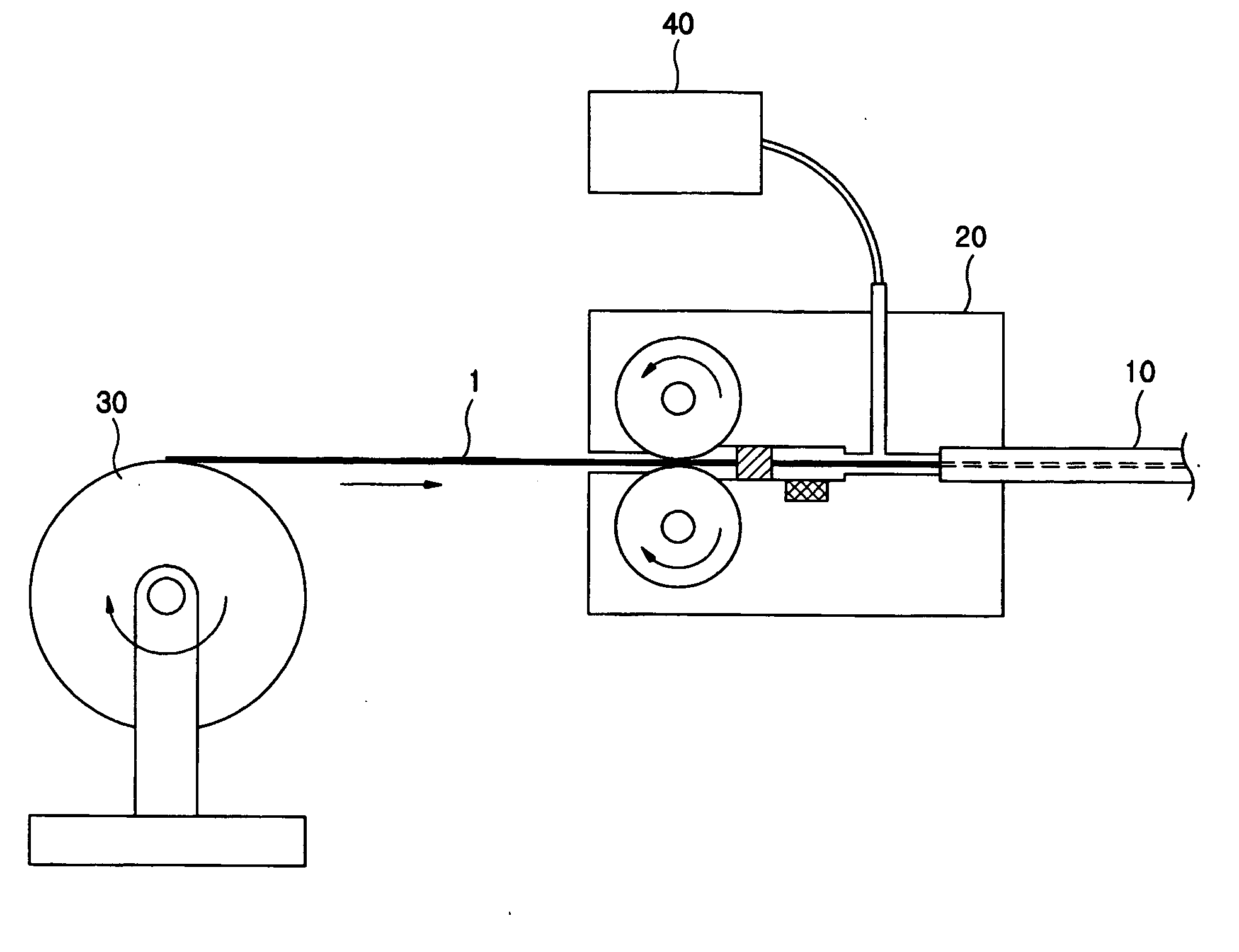
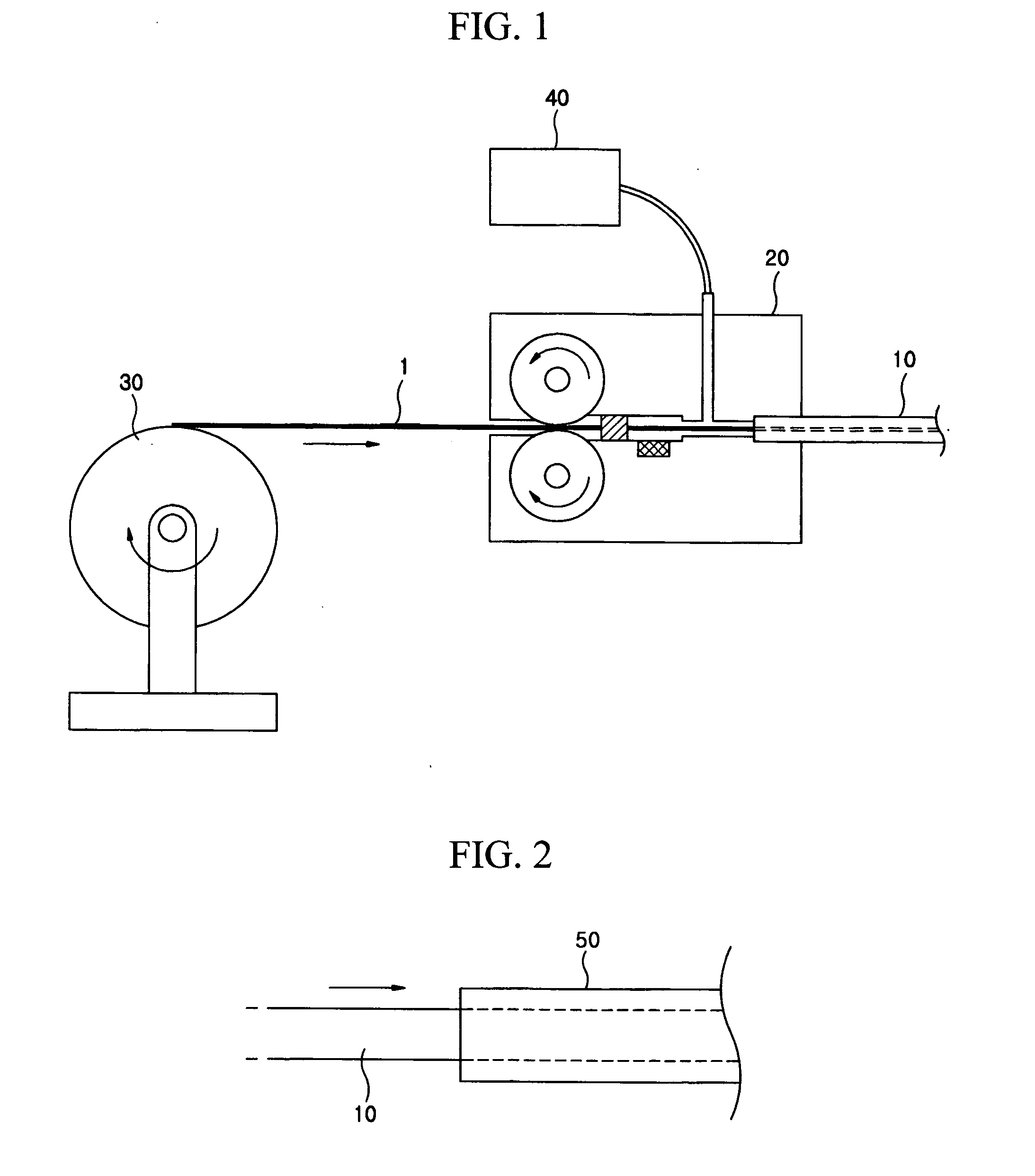
However, if the communication pipe 50 has a length longer than a certain level or communication lines such as UTP (Unshielded Twisted Pair) cable are already installed in the communication pipe 50, the installation tube 10 may not be easily installed due to the friction.

Method used


Image

  • Tube for installing an optical fiber unit having a lubricous surface
  • Tube for installing an optical fiber unit having a lubricous surface
  • Tube for installing an optical fiber unit having a lubricous surface

Examples


Embodiment Construction

[0022] Hereinafter, preferred embodiments of the present invention will be described in detail referring to the accompanying drawings. Prior to the description, it should be understood that the terms used in the specification and appended claims should not be construed as limited to general and dictionary meanings, but interpreted based on the meanings and concepts corresponding to technical aspects of the present invention on the basis of the principle that the inventor is allowed to define terms appropriately for the best explanation. Therefore, the description proposed herein is just a preferable example for the purpose of illustrations only, not intended to limit the scope of the invention, so it should be understood that other equivalents and modifications could be made thereto without departing from the spirit and scope of the invention.

[0023]FIG. 4 is a sectional view showing a tube for installing an optical fiber unit according to one embodiment of the present invention.

[0...


PUM


Abstract

Disclosed is a tube for installing an optical fiber unit having lubricous surface, which is installed in a communication pipe. The tube for installation includes an inner layer having lubricant components to decrease friction against an optical fiber unit, and an outer layer provided around the inner layer and composed of polymer having a lower friction coefficient than polyethylene so as to decrease friction when the tube is installed in the communication pipe. The tube is easier to install than the conventional one due to decreased friction against the communication pipe.

Description

TECHNICAL FIELD [0001] The present invention relates to an installation tube used for an optical fiber unit installation method using gas pressure. BACKGROUND ART [0002] An optical fiber unit installation method using gas pressure is installing a micro tube or duct for installation (hereinafter, referred to as ‘an installation tube’) at an optical fiber unit installation position in advance, and then installing an optical fiber unit into the installation tube with the use of gas pressure. This method allows easy installation and removal of an optical fiber unit and requires a low cost for construction, so it is widely used for installing an optical fiber unit in a narrow space like FTTH (Fiber To The Home). [0003] Generally in the gas pressure installation method, an optical fiber unit having 1- to 12-core optical fiber, called ABF (Air Blown Fiber), is inserted into the installation tube with the use of an optical fiber unit installation apparatus as shown in FIG. 1. [0004] Referri...

Claims


Application Information

Patent Timeline
Patent Type & Authority Applications(United States)
IPC IPC(8): G02B6/44G02B6/46
CPCG02B6/4459G02B6/46
Inventor LEE, BONG-HOONPARK, CHAN-YONGAHN, YEON-SU
Owner LG CABLE LTD (KR)
Why Eureka
Try Eureka