
Solid polymer fuel cell

Inactive Publication Date: 2007-05-03
NISSAN MOTOR CO LTD
View PDF7 Cites 4 Cited by
  • Summary
  • Abstract
  • Description
  • Claims
  • Application Information

AI Technical Summary

Benefits of technology

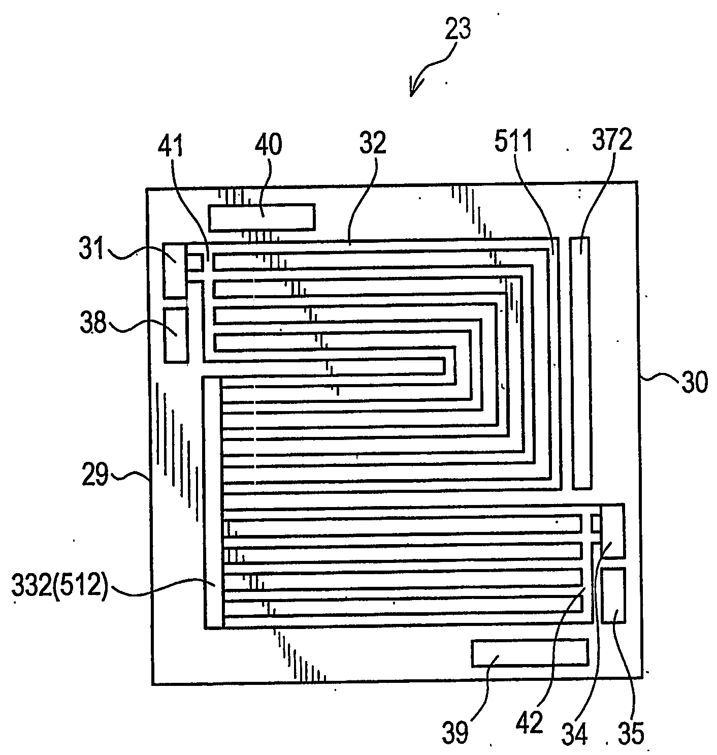
[0008] Regarding the prevention of flooding, JP 2000-100458 A and JP 2000-82482 A, published in the year 2000 by the Japan Patent Office, propose forming a through-hole in the fuel cell stack that communicates between the bent portions of the gas passages of the fuel cells. The through-hole helps to attain evenness of water contained in the anode gas and the cathode gas so that the surplus moisture in the cathode gas passages and the anode gas passages may not become excessive in particular fuel cells, which is desirable from the viewpoint of preventing flooding.
[0011] Further, in this fuel cell, in consideration for the arrangement of the manifold and the through-holes, the through-holes are provided in the middle flow portions of the anode gas passage and the cathode gas passage. Thus, in this fuel cell construction, it is difficult to prevent flooding in the downstream portions of the passages, which are most subject to flooding.
[0012] It is therefore an object of this invention to uniformize the water distribution in the fuel cell to thereby achieve an improvement in terms of flooding prevention performance.

Problems solved by technology

Thus, the portion of the anode gas passage in the vicinity of the inlet thereof, which is mostly liable to cause water shortage, is not superimposed on the portion of the cathode gas passage in the vicinity of the outlet thereof, which is mostly liable to cause flooding.
Thus, the portion of the anode gas passage in the vicinity of the outlet thereof, which is most subject to flooding, is not superimposed on the portion of the cathode gas passage in the vicinity of the inlet thereof, which is most subject to water shortage.
In this way, in this fuel cell, the water movement between the cathode and anode cannot be effected efficiently.
Thus, in this fuel cell construction, it is difficult to prevent flooding in the downstream portions of the passages, which are most subject to flooding.

Method used


Image

  • Solid polymer fuel cell
  • Solid polymer fuel cell
  • Solid polymer fuel cell

Examples


Embodiment Construction

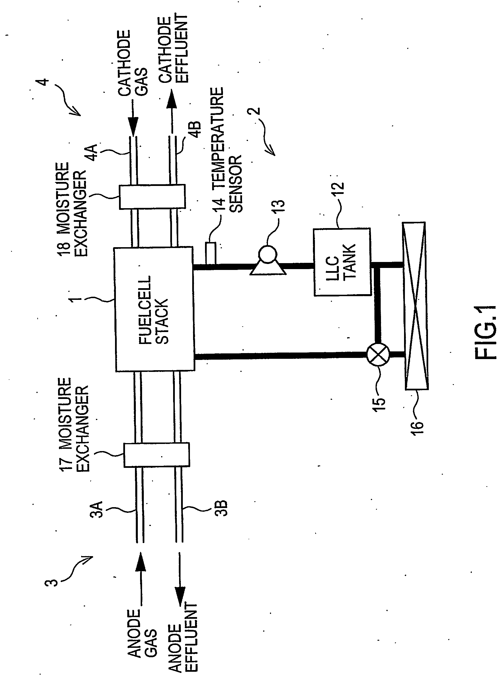
[0027] Referring to FIG. 1 of the drawings, a construction of a fuel cell system having a fuel cell stack 1 according to a, first embodiment of this invention will be described.

[0028] The fuel cell system comprises a fuel cell stack 1 that generates power through electrochemical reaction between an anode gas containing hydrogen and a cathode gas containing oxygen. Further, the fuel cell system comprises an LLC circulation system 2 that circulates an LLC (long life coolant) as a coolant through the fuel cell stack 1 to thereby keep the fuel cell stack 1 at an appropriate temperature. The LLC circulation system 2 circulates, as the LLC, an antifreeze obtained by mixing ethylene glycol and water with each other. The LLC circulation system 2 comprises an LLC tank 12, an LLC pump 13, a temperature sensor 14, a bypass valve 15, and a radiator 16.

[0029] The opening of the bypass valve 15 is controlled according to the output of the temperature sensor 14 to adjust the flow rate of the LLC...


PUM


Abstract

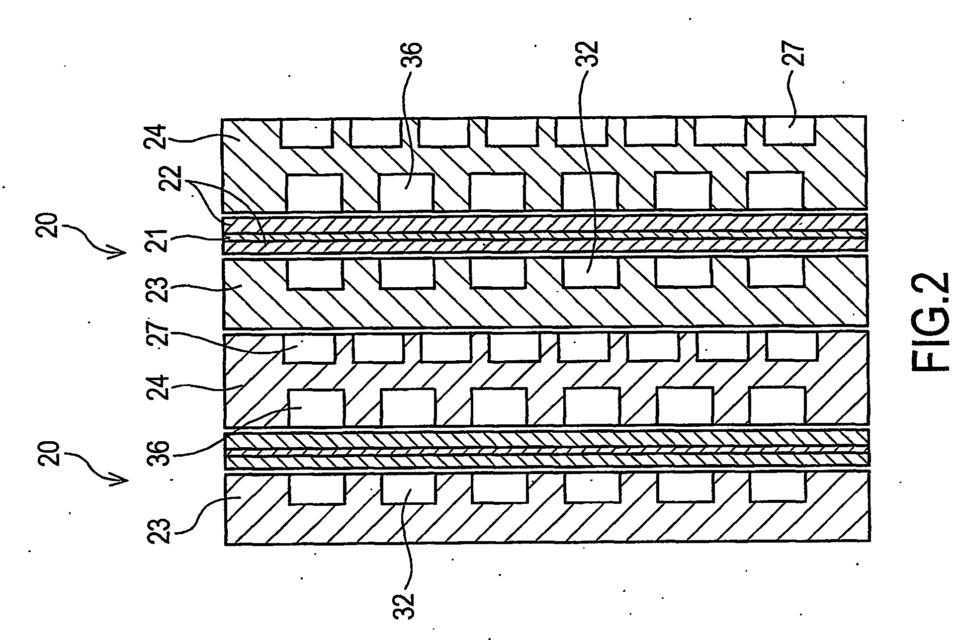
Fuel cells (20) are superimposed one upon the other in the stacking direction. Each fuel cell (20) comprises an anode gas passage (32) and a cathode gas passage (36). Each passage has a meandering configuration provided with two or more bent portions (511, 512, 521, 522). At least the most downstream bent portion (512, 522) of at least one of the anode gas passage (32) and the cathode gas passage (36) is connected to a through-hole (332, 372) extending through the fuel cell stack (1) in the stacking direction of the fuel cells (20). The through hole (332, 372) averages out the condensed water in the anode gas passages (32 )or the cathode gas passages (36) and prevents flooding from being caused in a specific anode gas or cathode gas passage.

Description

FIELD OF THE INVENTION [0001] This invention relates to separators of a solid polymer fuel cell and a configuration of passages provided therein. BACKGROUND OF THE INVENTION [0002] A solid polymer fuel cell stack comprises a plurality of fuel cells stacked together in one direction. Each fuel cell is composed of a membrane electrode assembly and separators sandwiching the membrane electrode assembly. A membrane electrode assembly comprises an electrolyte membrane with an anode and a cathode respectively arranged on either side thereof. The separator in contact with the anode has a passage for an anode gas whose main component is hydrogen, and the separator in contact with the cathode has a passage for a cathode gas containing oxygen. [0003] The fuel cell generates power through electrochemical reaction through the electrolyte membrane between hydrogen supplied to the anode and oxygen supplied to the cathode. To cause this electrochemical reaction, the electrolyte membrane requires a...

Claims


Application Information

Patent Timeline
IPC IPC(8): H01M8/02H01M8/04H01M8/10H01M8/24
CPCH01M8/0263H01M8/0267H01M8/04029H01M8/04119H01M8/04141H01M8/04156H01M8/04291H01M8/24Y02E60/50H01M8/2483
Inventor YOSHIZAWA, KOUDAIMIYAKUBO, HIROSHI
Owner NISSAN MOTOR CO LTD
Learn More