Steerable catheter devices and methods of articulating catheter devices

Active Publication Date: 2007-05-03
COOK MEDICAL TECH LLC
View PDF12 Cites 89 Cited by
  • Summary
  • Abstract
  • Description
  • Claims
  • Application Information

AI Technical Summary

Benefits of technology

[0021] Another embodiment includes a catheter having an elongated intermediate portion extending from a first end portion to a flexible second end portion and defining a central longitudinal axis. The flexible second end portion comprises a steerable distal tip portion. Two or more elongate chamber bodies are arranged about the longitudinal axis, with each of the two or more chamber bodies having a fluid flow channel from a proximal opening located at or near the first end portion and terminating at a distensible occluded distal end located at or near the steerable distal tip portion. A fluid actuator operably connects at or near the first end portion and is in communication with at least one of the proximal openings of the fluid flow channels, and is capable of controlling a supply of fluid to and from the at least one fluid flow channel. In response to a change in fluid pressure, the distensible occluded distal end

Problems solved by technology

Maneuvering the catheter second end through the vessel passageway and to the target site often presents a time-consuming endeavor for the physician.
Any of these steps increases the length of time for the medical procedure and possibly patient discomfort.
Also, as the catheter is inserted deeper and deeper into a patient, and as the catheter navigates through a tortuous pathway of vessel openings, catheter rotation may become more difficult and may present the patient with some discomfort.
Moreover, a cable typically extends through a substantial length of the catheter, which cable length tends to increase the variable that the catheter may kink, buckle, bow, or prolapse as a result of the tortuous path the procedure may require.
One problem they would have with fluid forced steerable catheters is the tendency to balloon the fluid actuating lumen as fluid is forced through the actuating lumen to the di

Method used


Image

  • Steerable catheter devices and methods of articulating catheter devices
  • Steerable catheter devices and methods of articulating catheter devices
  • Steerable catheter devices and methods of articulating catheter devices

Examples


Embodiment Construction

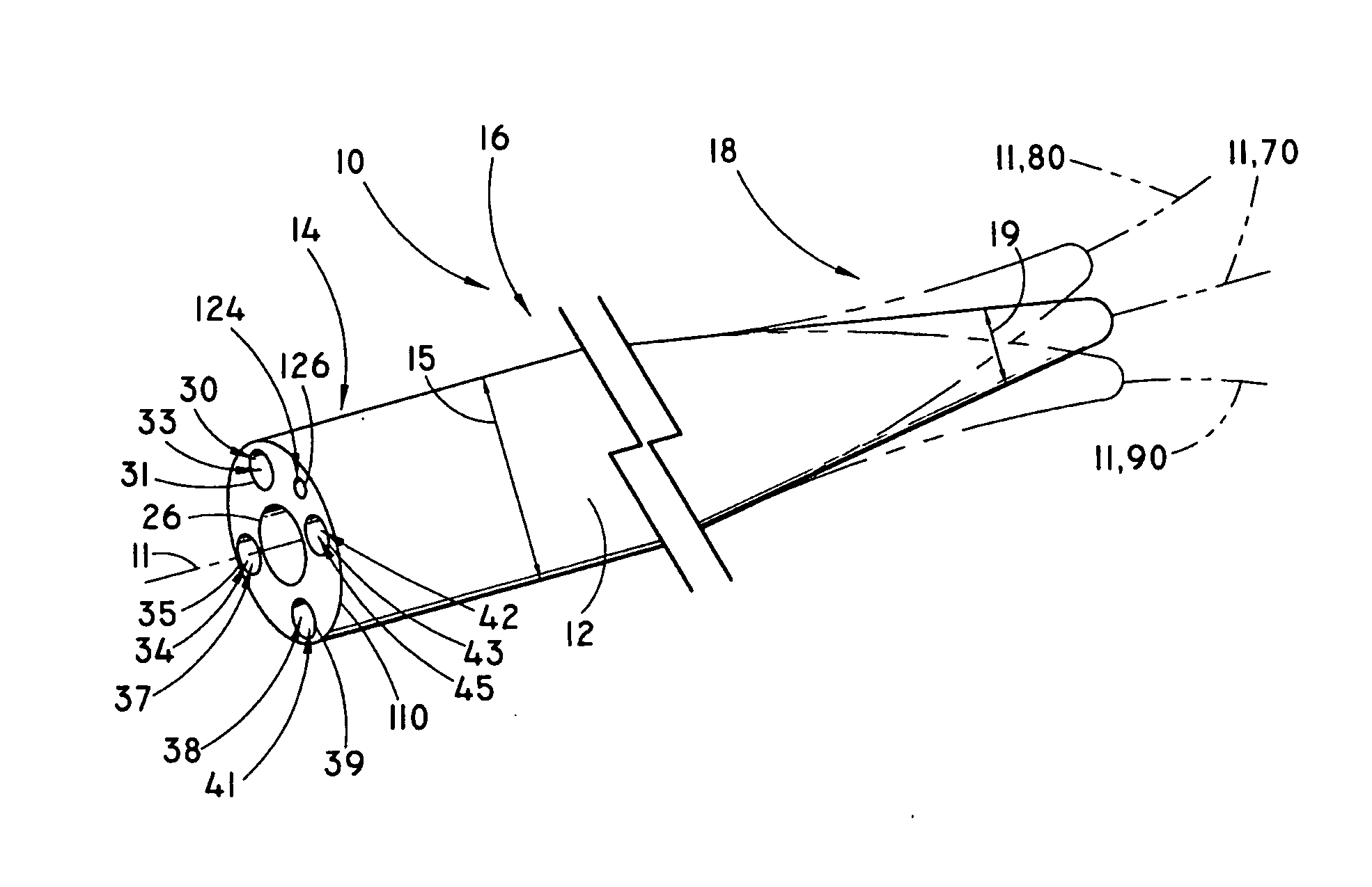
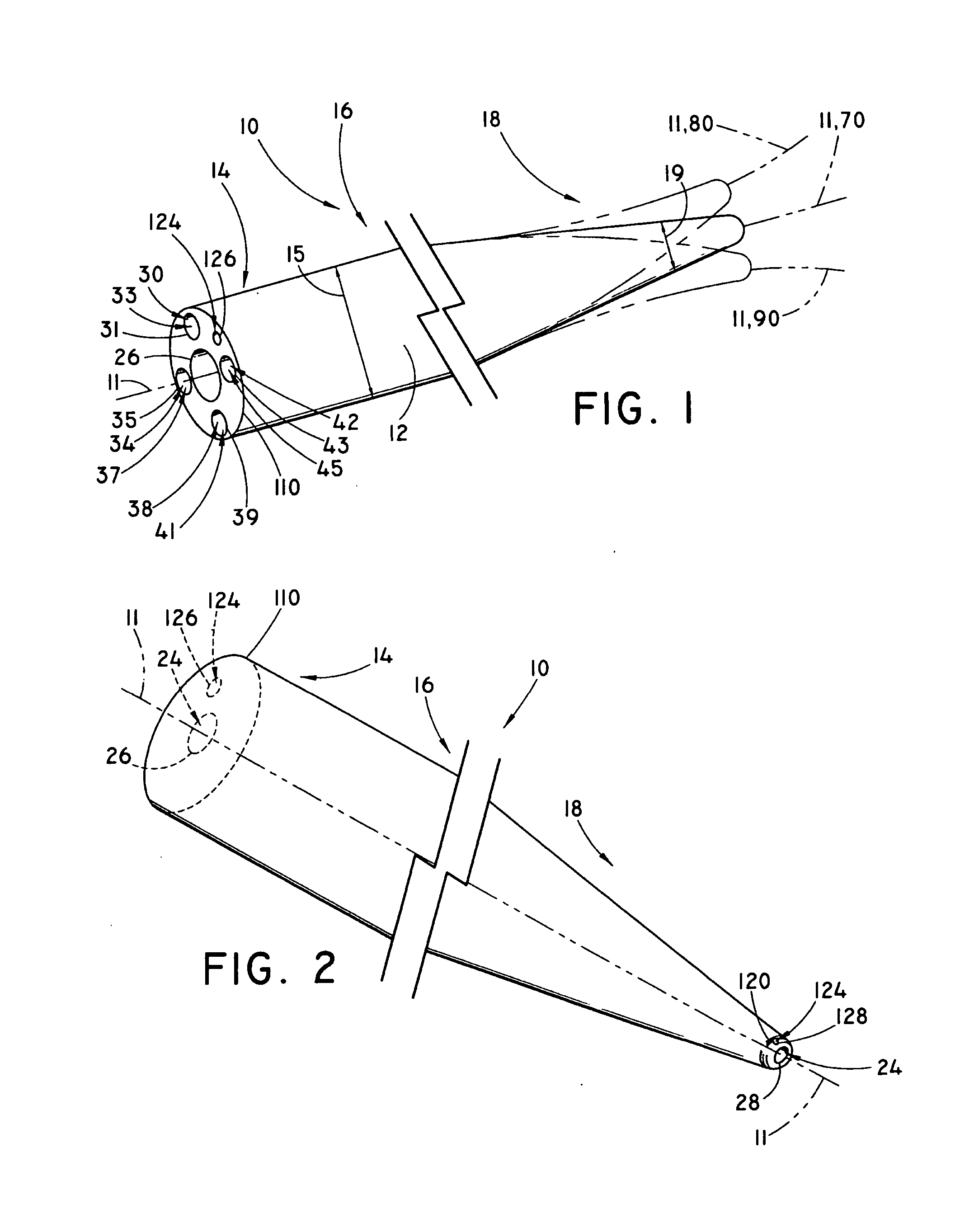
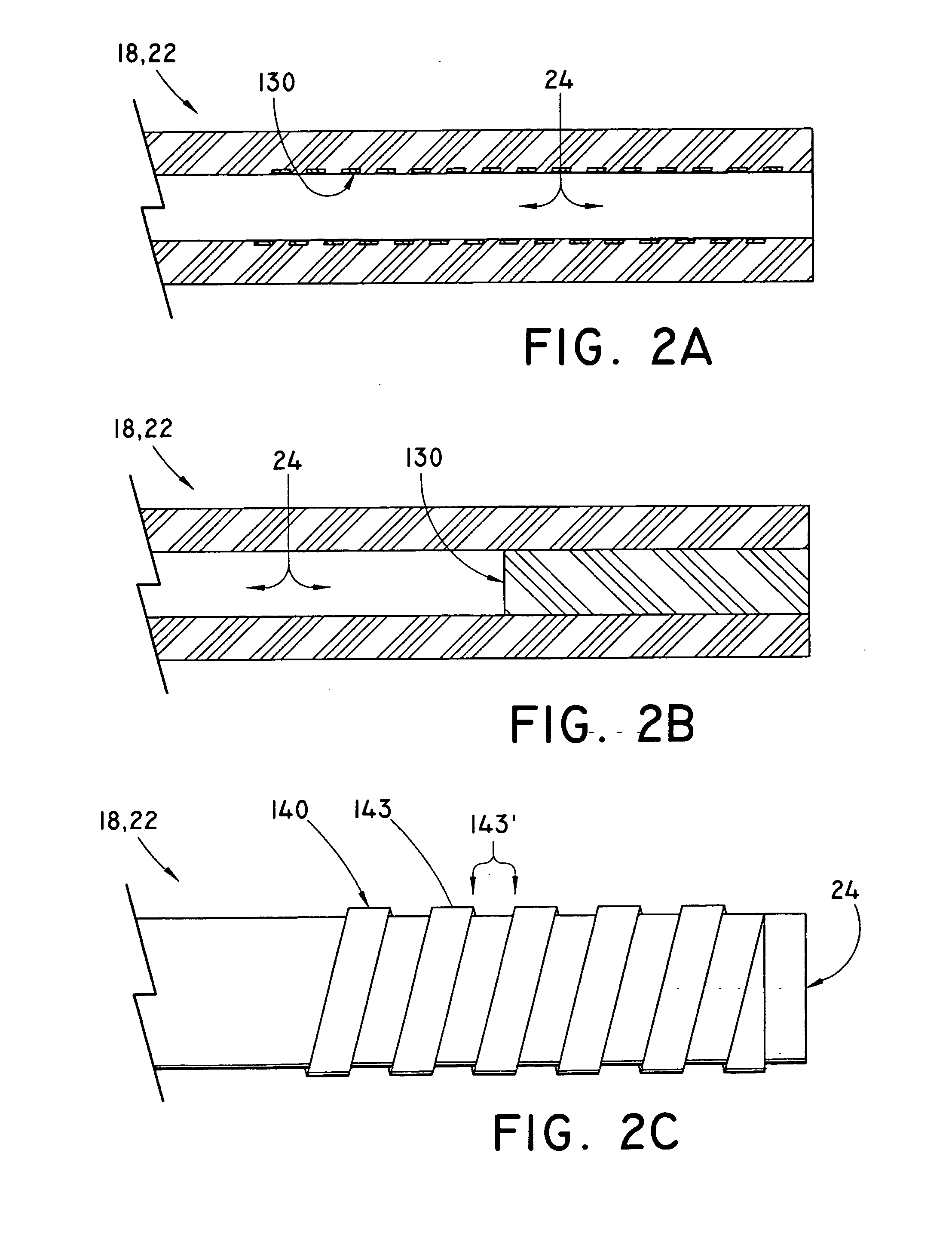
[0043] Although not limited in its scope or applicability, the present inventions relate generally to steerable catheter devices used percutaneously, through an endoscope working channel, or through an accessory channel used with an endoscope. More particularly, and by way of illustration and not by way of limitation, the present inventions relate to steerable catheter devices comprising one or more channels having an occluded distal end at or near a flexible second end portion of the catheter. The occluded distal end distends axially under an internal fluid pressure, and thereby deflects and steers the device.

[0044] For the purpose of promoting an understanding of the principles of the invention, the following provides a detailed description of embodiments of the invention as illustrated by the drawings as well as the language used herein to describe the aspects of the invention. The description is not intended to limit the invention in any manner, but rather serves to enable thos...


PUM


Abstract

Steerable catheter devices are provided having a proximal first end portion, an elongate intermediate portion, and a distal flexible second end portion defining a longitudinal axis, and at least one channel having a proximal opening and terminating at an occluded distal end radially offset relative to the central longitudinal axis and positioned within the catheter flexible second end portion substantially straight in a relaxed position and bent when the occluded distal end is under a change in internal fluid pressure. Optionally, the catheter further has a dye injection lumen and a tool receiving passageway extending from the first end portion to the second end portion. The occluded distal end is axially elastically distensible under an internal fluid pressure to deflect (thereby to steer) the catheter second end portion through the tortuous path of a vessel passageway when used percutaneously or working channel of an endoscope or endoscope accessory device.

Description

RELATED APPLICATIONS [0001] The present patent document claims the benefit of the filing date under 35 U.S.C. §119(e) of U.S. Provisional Patent Application filed on Oct. 31, 2005 entitled, “Steerable Catheter Devices and Methods of Articulating Catheter Devices,” and having an application Ser. No. 60 / 731,763, the disclosure of which is hereby incorporated by reference in its entirety.FIELD OF THE INVENTION [0002] The present invention relates to catheter devices for use with endoscopes or percutaneously with vascular medical devices and the like, wherein the catheters employ fluids used to steer the distal tip of the catheter. BACKGROUND OF THE INVENTION [0003] Physicians and other healthcare professionals (collectively, “physician”) commonly use catheters in a variety of medical procedures. Catheters guide and introduce a variety of medical devices, guide wires, drug delivery tools, therapeutic agents (e.g., drugs, medication, narcotics, antibiotics, pharmaceutical products, and / o...

Claims


Application Information

Patent Timeline
IPC IPC(8): A61M25/00A61B1/00A61B6/00
CPCA61B1/0051A61B6/481A61B6/504A61B2017/003A61M25/0105A61M25/0136A61M25/0141A61M25/0155
Inventor KENNEDY, KENNETH C. II
Owner COOK MEDICAL TECH LLC
Why Eureka
Try Eureka