Computer method and apparatus for connection creation in a software modeling system

a software modeling and computer method technology, applied in the field of computer programming, can solve problems such as difficult to provide hints as to what, difficult to use, and cluttered shape borders

Inactive Publication Date: 2007-05-03
IBM CORP
View PDF31 Cites 20 Cited by
  • Summary
  • Abstract
  • Description
  • Claims
  • Application Information

AI Technical Summary

Problems solved by technology

One of the problems with many visual modeling applications is that they are difficult to use.
It is also difficult to provide hints as to what types of things the user should be creating (e.g., what types of connectors should go between certain shapes).
The problem is that for shapes that support a lot of relationships, the border of the shape can get quite cluttered.
This leads to some usability issues which ironically is what the connector handles are trying to solve.
First, when the handles are invoked, this creates an “explosion” of handles around the shape which can cause the user to be inhibited by the choices available.
Often the user won't understand the symbolic meaning of the handles and just know that a relationship needs to be created.
This means that the user interface (UI) for the handles becomes inconsistent across shapes and semantic domains.
As a result the user does not gain a familiarity of the UI across all shapes and needs to learn the available handles and positions on a per shape basis.
Another issue is that typically these handles are only available for source to target relationship creation.
This partially defeats the purpose of the handles in that it is forcing movement of the mouse when a contributor to the relationship was literally under hand!
A similar issue is if the target of the mouse cursor is on the opposite side of the source shape from the connector handle, the user is required to move the cursor across the source shape to the connector handle and drag across the source shape to the target.
This feels awkward since the source shape effectively gets in the way of the gesture and forces redundant mouse / cursor movement.

Method used


Image

  • Computer method and apparatus for connection creation in a software modeling system
  • Computer method and apparatus for connection creation in a software modeling system
  • Computer method and apparatus for connection creation in a software modeling system

Examples


Embodiment Construction

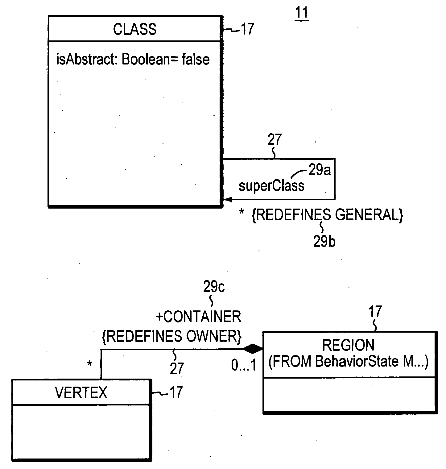
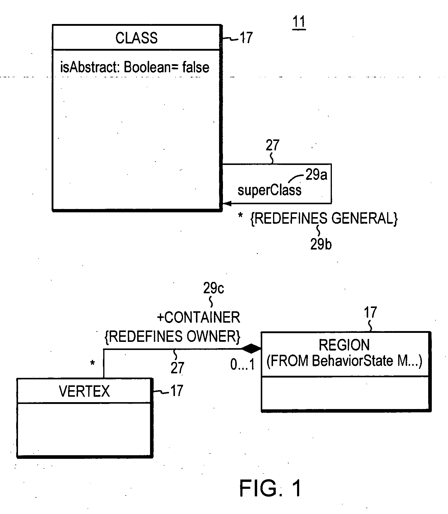
[0023] Illustrated in FIG. 1 is an example UML diagram 11 providing a model representation of a software program under design and / or consideration. Squares and other box-like shapes (or generally, model elements) 17 represent program elements such as classes and object instances of classes. Lines connecting the various shapes indicate relationships and constraints between program elements. These lines are referred to (in the art) as “connectors”27. Properties 29 of the classes and object instances are also indicated along the connectors 27.

[0024] More formally, a relationship is a connection between model elements. A UML relationship is a type of model element that adds semantics to models. A user can add and modify relationships in models to identify the semantic ties between model elements 17.

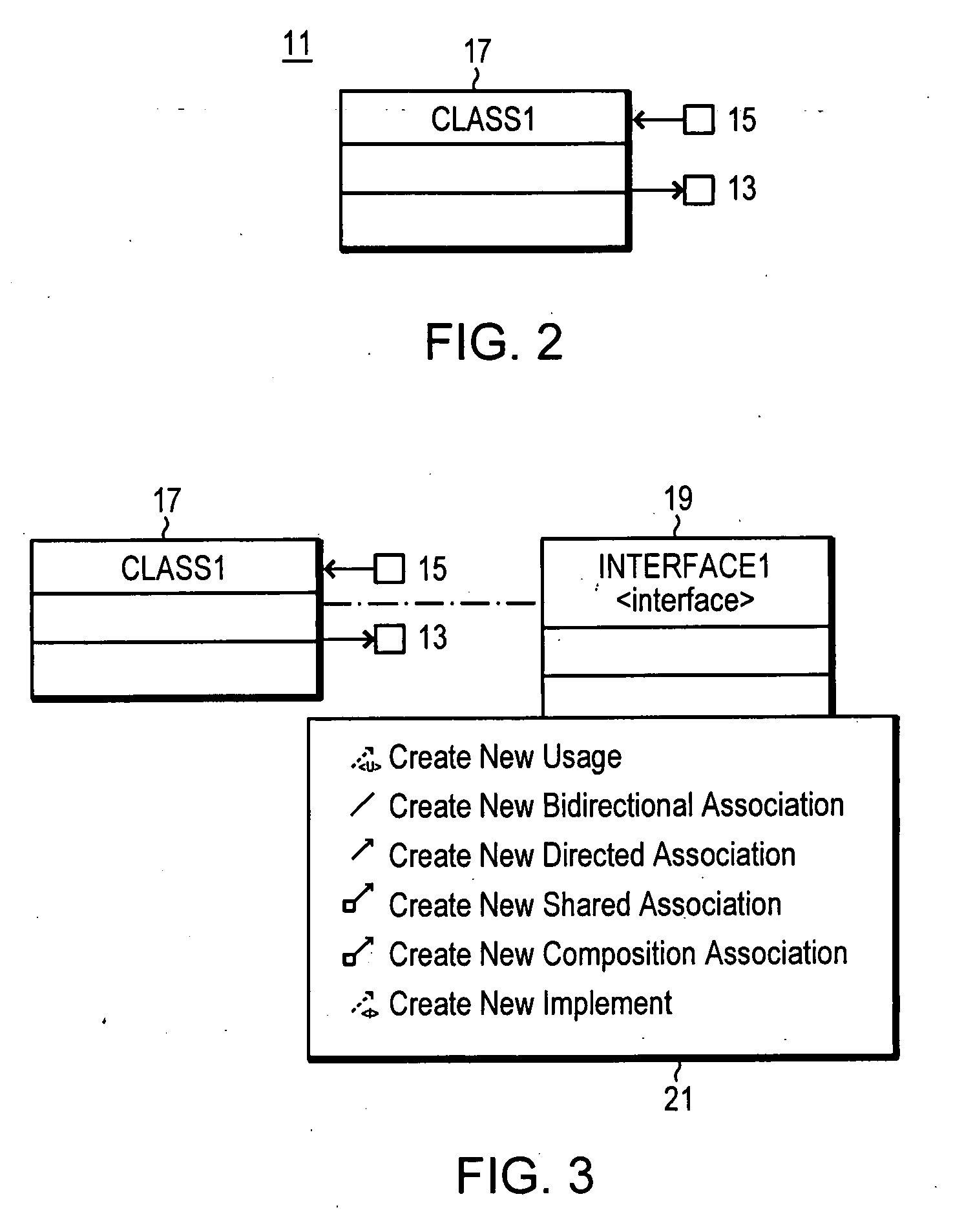
[0025] In a modeling application, a user drags and drops visual modeling (UML) elements from a palette to a working diagram. In a preferred embodiment of the present invention, two connecto...


PUM


Abstract

A user interface for creating relationships between visual modeling (e.g., UML) elements on a diagram is disclosed. The user interface utilizes two connector handles that represent “source to target” and “target to source” relationships. The connector handles are consistent across all shapes / elements in the diagram and are made to appear on the edge of an element shape nearest to the cursor. The source to target connector handle is used for gestures involving outgoing connections. The target to source connector handle is used for gestures involving incoming connections. The user creates a new relationship between a source and a target by selecting one of the connector handles on the source shape and dragging to the target context (element shape or blank area). Next the user is prompted to qualify the gesture by selecting from a menu the type of relationship desired to be created. A connection or edges in the diagram of the type representative of the user's selections is produced.

Description

BACKGROUND OF THE INVENTION [0001] In the art of computer programming, there are various tools to assist with the designing of a software program (e.g. application program). One category of such program design tools is the visual modeling type. The UML is an example visual modeling language (with formal syntax and semantics) for communicating a model or conceptionalization. The modeling language specification specifies modeling elements, notation and usage guidelines and not order of activities, specification of artifacts, repository interface, storage, run-time behavior and so forth. [0002] In general, at the modeling level a “problem” is posed in terms of a customer's needs and requirements and may be referred to as the business problem system. The software designer develops a “solution” software product and or service that addresses the problem. The UML syntax enables software designers to express (specify and document) the subject problems and solutions in a standardized manner,...

Claims


Application Information

Patent Timeline
Patent Type & Authority Applications(United States)
IPC IPC(8): G06F9/44
CPCG06F8/34
Inventor MAHONEY, CHERIE L.SHAW, STEVEN R.
Owner IBM CORP
Why Eureka
Try Eureka