
Magnetic fishing tool and method

a magnet fishing and tool technology, applied in the field of metal object retrieval apparatus, can solve the problems of inability to meet the needs of the metal object retrieval field,

Active Publication Date: 2007-05-10
VENTURI OIL TOOLS
View PDF39 Cites 7 Cited by
  • Summary
  • Abstract
  • Description
  • Claims
  • Application Information

AI Technical Summary

Benefits of technology

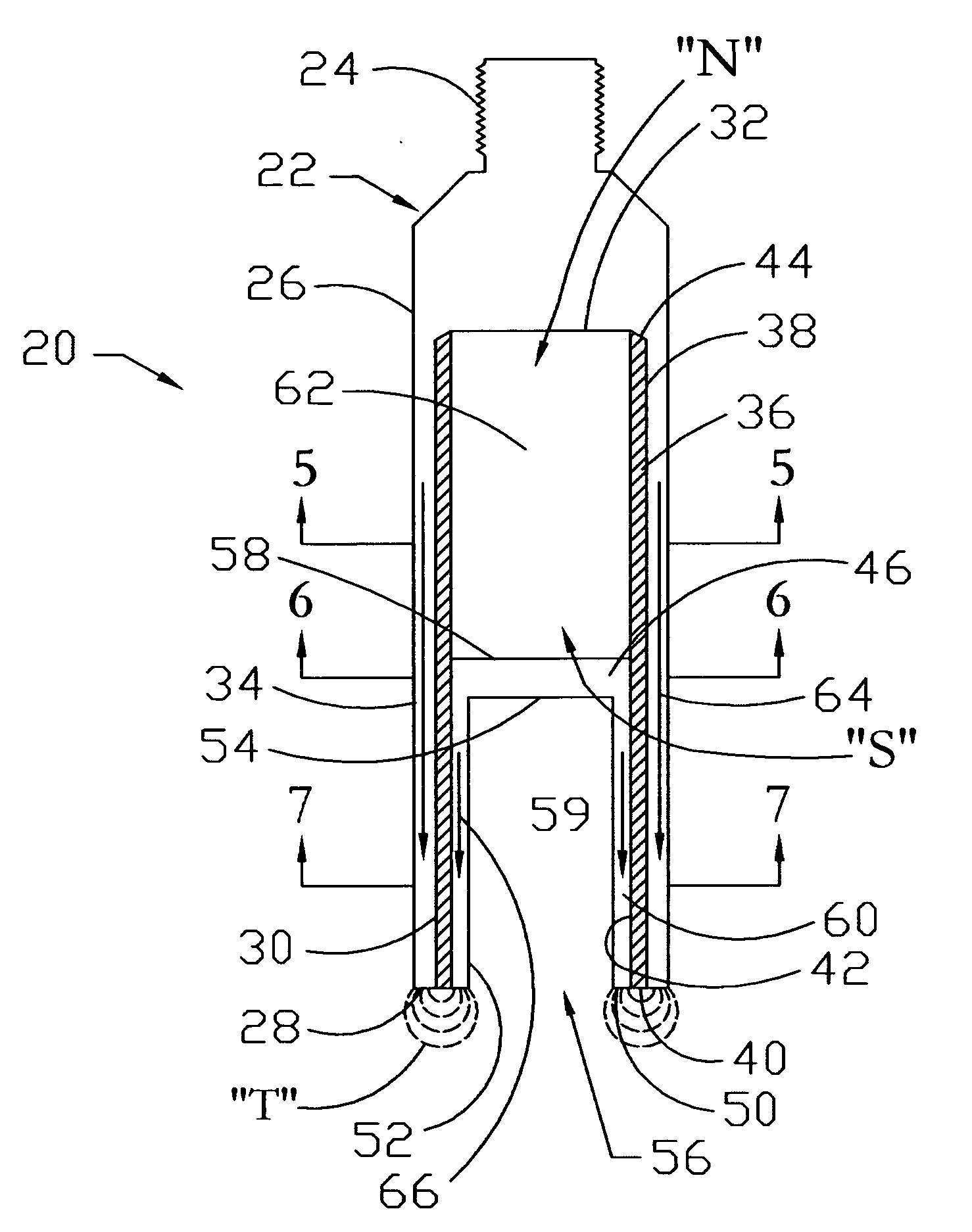
[0010] An advantage of the present invention is the ability of the apparatus to focus the magnetic field in a pattern compatible to well bore fishing applications. In other words, the toroidal magnetic field pattern has an annular cross-sectional area. Yet another advantage is that the magnetic lines of flux are focused in a toroidal shape.
[0011] A feature of the present invention is that the magnetic field strength may be varied by changing the size of magnet or the material of the magnet. Still yet another feature is that the operator can effect magnetic field strength by varying size of housing, sleeve and container. Another feature is that the apparatus can be run on wire line, electric line, coiled tubing and other tubulars.
[0012] Yet another feature is that the design of the container allows for the shaping of the toroidal shaped magnetic field. Another feature is that the cavity of the container allows for placement of the fishing neck during the fishing operation. Still yet another feature is the container allows for the shaping of the toroidal shaped magnetic field.

Problems solved by technology

As well understood by those of ordinary skill in the art, during the course of drilling, completing, and producing, objects may become lost within the well bore.
As well known in the art, very costly well bores may have to be scraped and / or sidetracked due to these types of fish.
However, all of the present magnet fishing tools have inherent problems and limitations.

Method used


Image

  • Magnetic fishing tool and method
  • Magnetic fishing tool and method
  • Magnetic fishing tool and method

Examples


Embodiment Construction

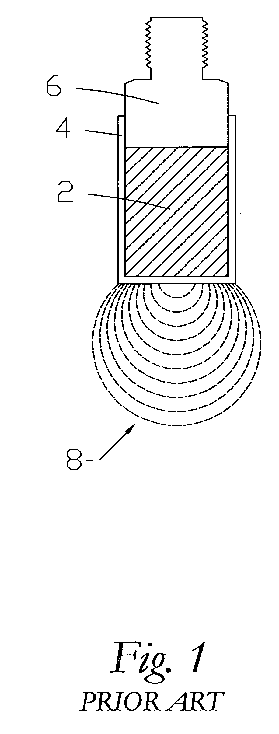
[0023] Referring now to FIG. 1, a partial cross-sectional view of a prior art magnet will now be described. Prior art magnets contained a generally cylindrical magnet 2 that was encased in a cylindrical container 4. The cylindrical container 4 was attached to an adapter sub 6, and wherein the adapter sub 6 can then be attached to a work string, such as wire line, electric line, coiled tubing or other tubulars. FIG. 1 depicts the magnetic lines of flux created by the prior art design, with the magnetic lines of flux being denoted by the numeral 8. As shown in FIG. 1, the magnetic lines of flux emanate in a spherical fashion from the magnet 2.

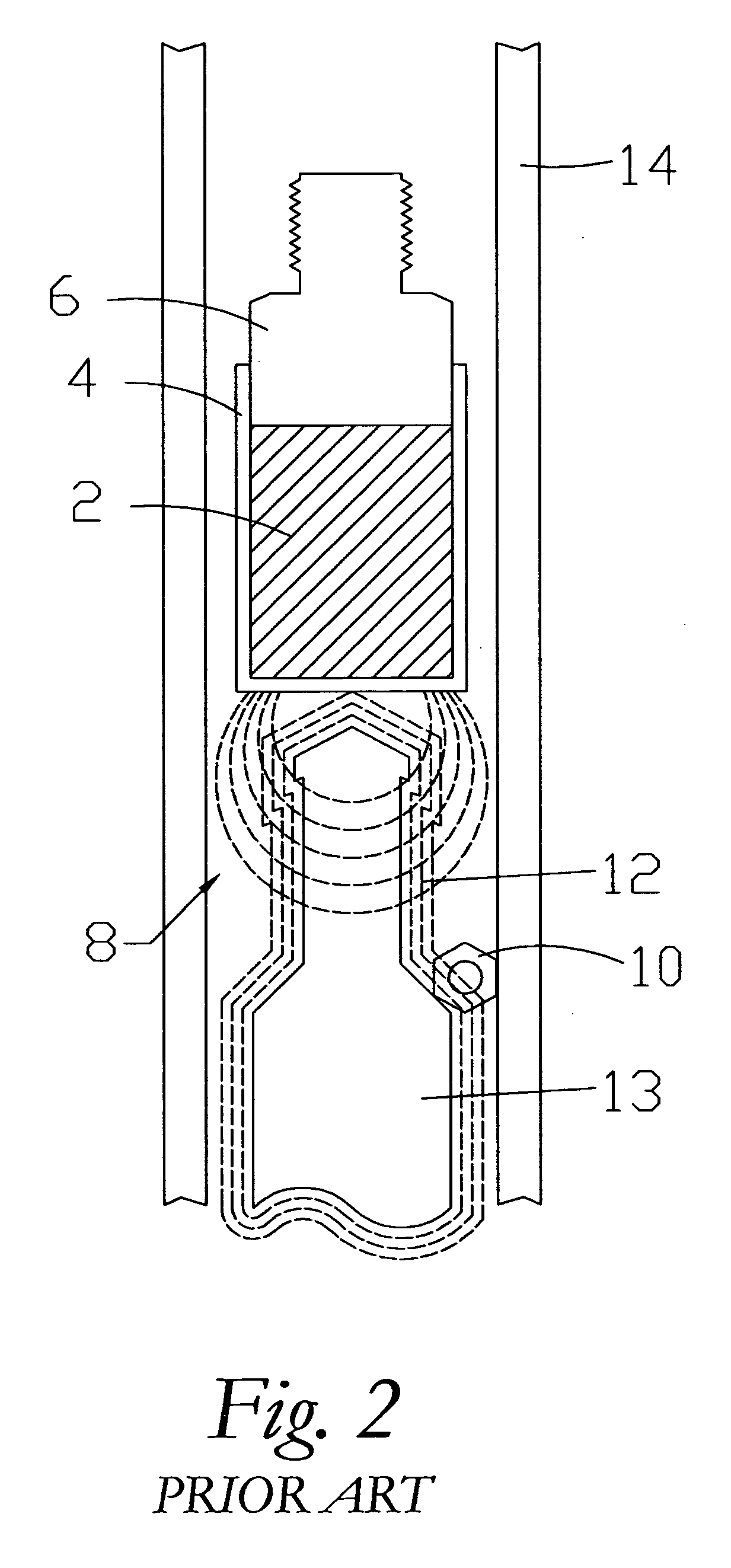
[0024]FIG. 2 is a partial cross-sectional view of the prior art tool of FIG. 1 in the operation of retrieving a down hole fish 10. It should be noted that like numbers appearing in the various figures refer to like components. In this case, the down hole fish 10 is a bolt that is positioned on top of a fishing neck 12 of a down hole tool 13 in a...


PUM


Abstract

An apparatus for retrieving metal objects. The apparatus includes a housing with an inner part, with the housing having a first wall. The apparatus further includes a sleeve disposed within the housing, with the sleeve being constructed of a non-magnetic conduction material. A magnet is disposed within the sleeve, with the magnet having a north pole and a south pole. The apparatus further includes a container disposed within the sleeve, the container having a second wall. In the most preferred embodiment, the first wall defines a first pathway for magnetic lines of flux for the north pole of the magnet and wherein the second wall defines a second pathway for magnetic lines of flux for the south pole of the magnet so that a toroidal magnetic field is formed about the distal end of the sleeve. A method of retrieving a metal object within a well bore is also disclosed.

Description

BACKGROUND OF THE INVENTION [0001] This invention relates to an apparatus for retrieving metal objects. More specifically, this invention relates to a fishing apparatus for retrieving metal objects from a well bore. [0002] In the search for hydrocarbons, an operator will drill a subterranean well bore. The well bore may be cased with a casing string, and thereafter, completed to a hydrocarbon reservoir. As well understood by those of ordinary skill in the art, during the course of drilling, completing, and producing, objects may become lost within the well bore. These objects are known as fish, and as the name implies, operators many times find it highly desirable to retrieve these fish. [0003] Sometimes, the fish may be large metal objects such as packers, plugs, valves, etc. However, smaller objects, such as metal shavings, nuts, bolts, pieces of hand tools, etc, also find there way into the well bore. As well known in the art, very costly well bores may have to be scraped and / or ...

Claims


Application Information

Patent Timeline
IPC IPC(8): E21B31/06
CPCE21B31/06
Inventor GAZEWOOD, MICHAEL J.
Owner VENTURI OIL TOOLS
Learn More