Supercharge Your Innovation With Domain-Expert AI Agents!

System and method of mitigating effects of component deflection in a probe card analyzer

a probe card analyzer and component deflection technology, applied in the field of probe card analyzers, can solve the problems of increasing the apparent planarity of higher probes, deficient current implementation systems and methods, and insufficient correlation of traditional methodologies, so as to effectively load” the effect of planarity measurements

Active Publication Date: 2007-05-10
ONTO INNOVATION INC
View PDF28 Cites 2 Cited by
  • Summary
  • Abstract
  • Description
  • Claims
  • Application Information

AI Technical Summary

Benefits of technology

The present invention provides a system and method for measuring the effects of component deflections in a probe card analyzer system. The system combines non-bussed electrical planarity measurements with fast optical planarity measurements to produce "effectively loaded" planarity measurements. The method includes computing planarity effects due to fiducial plate deflection, combining planarity effects due to probe card deflection and probe card fixture deflection, and responsively calculating a load compensated planarity for the probe card. The system and method may also account for planarity effects due to stage deflection and may further identify and measure fiducial plate deflection at different non-bussed probe locations. The technical effects of the invention include improved accuracy and efficiency in measuring probe card planarity and reduced errors in analyzing probe card performance.

Problems solved by technology

This is due to the fact that the loads arising from contact with lower probes cause deflection, which in turn increases the apparent planarity of higher probes.
Currently implemented systems and methods are deficient in that traditional methodologies do not accurately correlate optical planarity measurements, which are made in the absence of contact loads, to electrical planarity measurements, which are made in the presence of, and are influenced by, such contact loads.

Method used


Image

  • System and method of mitigating effects of component deflection in a probe card analyzer
  • System and method of mitigating effects of component deflection in a probe card analyzer
  • System and method of mitigating effects of component deflection in a probe card analyzer

Examples


Embodiment Construction

[0021] By way of general background, it will be appreciated that the approach to obtaining optical planarity measurements generally known in the art and set forth by way of example herein is that of three-dimensional comparative metrology using a substantially transparent fiducial substrate, e.g., a glass, acrylic, quartz, or other suitably transparent fiducial plate as set forth in more detail below. While an exemplary three-dimensional comparative metrology technique is described below, other optical planarity assessment methods may be known or developed in accordance with generally known principles. The following description is provided by way of example only and not by way of limitation; the present disclosure is not intended to be limited to any particular method of performing an optical planarity analysis.

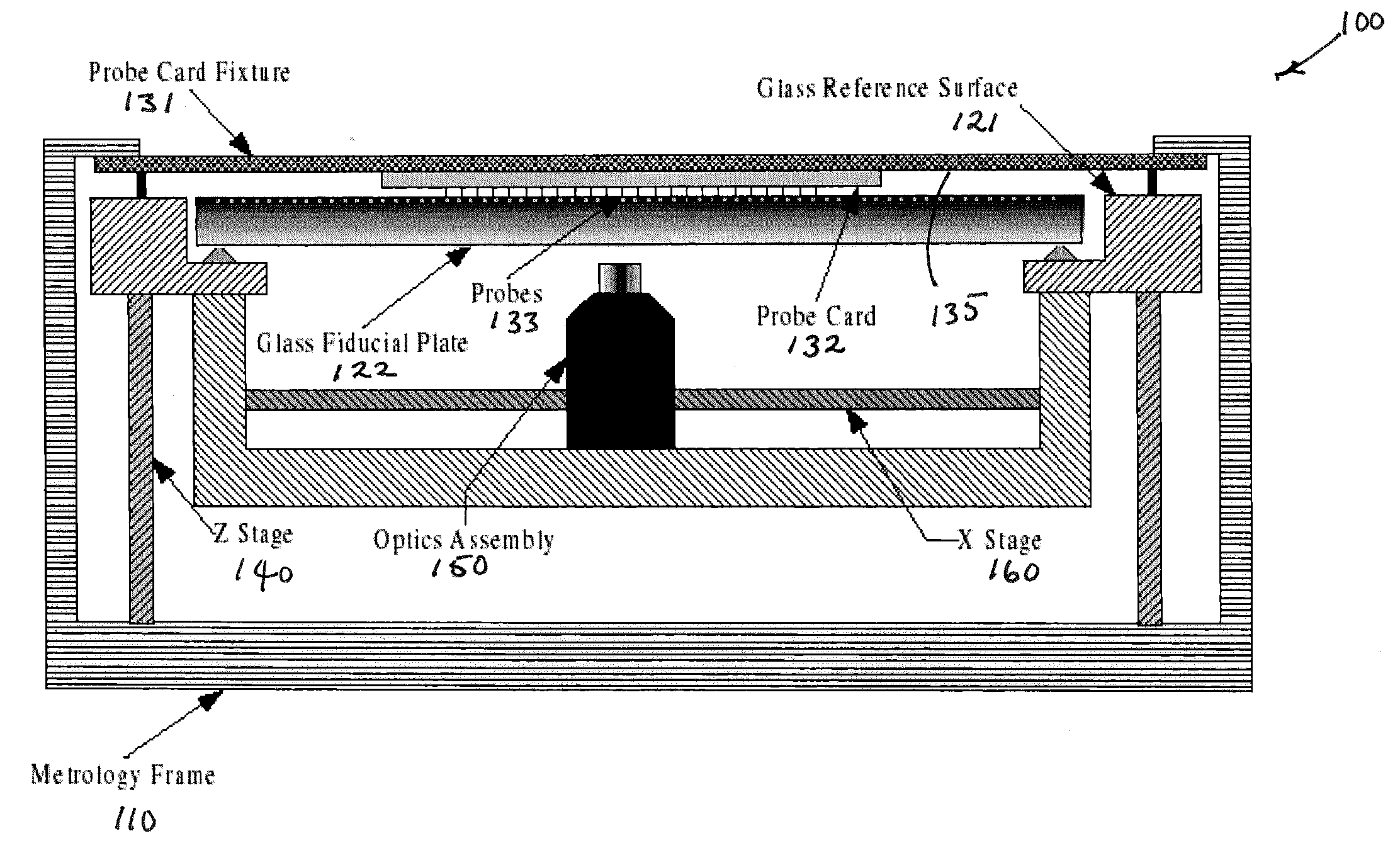
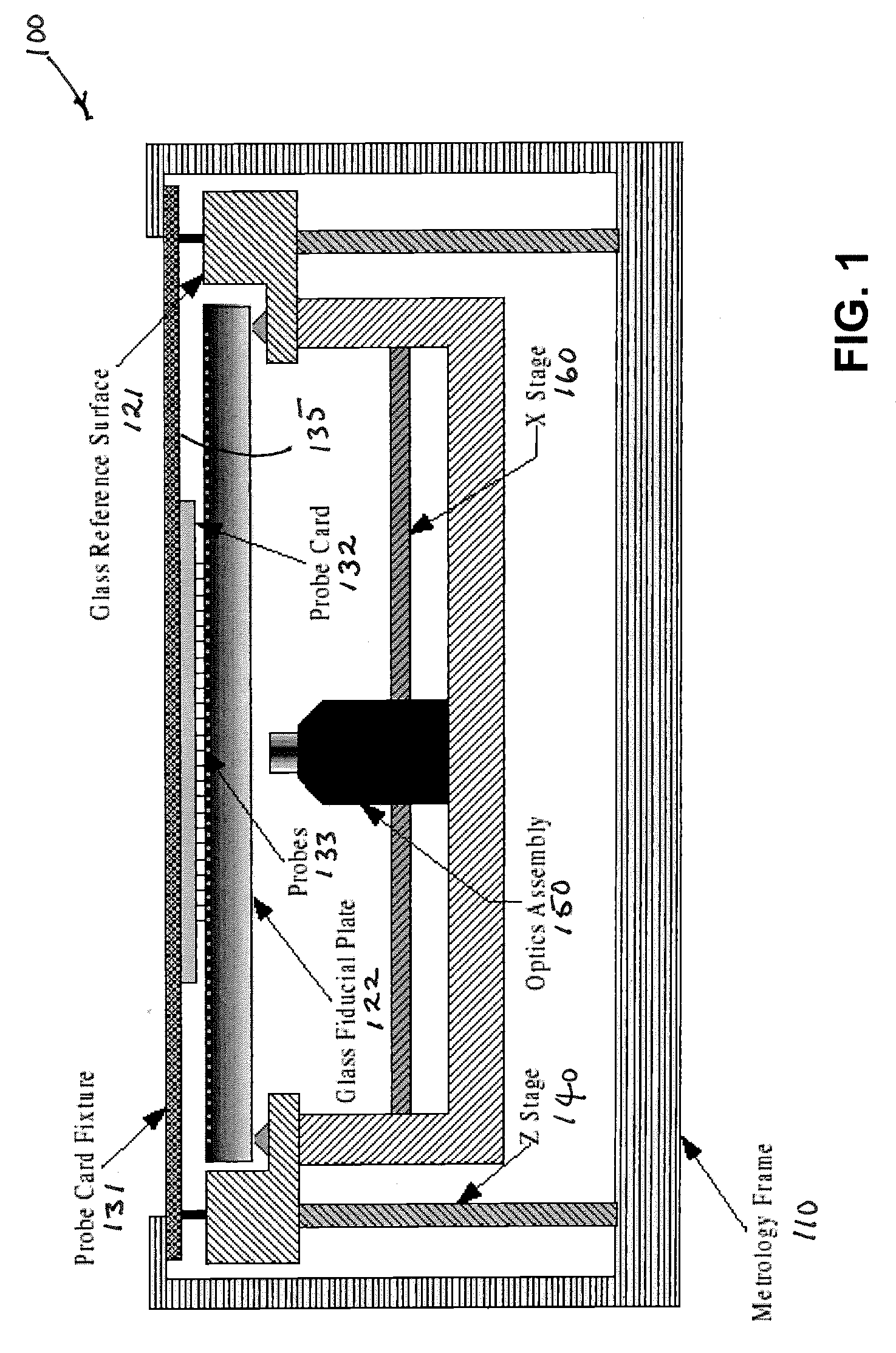
[0022]FIG. 1 is a simplified block diagram illustrating components of one embodiment of a probe card analyzer system. As is generally known in the art, system 100 may compri...


PUM


Abstract

A system and method of mitigating the effects of component deflections in a probe card analyzer system may implement three-dimensional comparative optical metrology techniques to model deflection characteristics. An exemplary system and method combine non-bussed electrical planarity measurements with fast optical planarity measurements to produce “effectively loaded” planarity measurements.

Description

CROSS-REFERENCE TO RELATED APPLICATIONS [0001] The present application claims the benefit of U.S. provisional application Ser. No. 60 / 454,574, filed Mar. 14, 2003, entitled “MITIGATING THE EFFECTS OF PROBE CARD / FIXTURE AND METROLOGY BASE DEFLECTION IN A PROBE CARD ANALYZER,” the disclosure of which is hereby incorporated herein by reference in its entirety.FIELD OF THE INVENTION [0002] Aspects of the present invention relate generally to the field of probe card analyzers, and more particularly to a system and method of mitigating the effects of component deflections in a probe card analyzer system. BACKGROUND OF THE INVENTION [0003] Traditional probe card analyzers measure probe planarity by electrical means, and generally measure probe alignment by optical means. Electrical planarity measurements are typically made by slowly bringing a conductive contact surface into contact with the probes on a probe card. In that regard, the conductive contact surface is moved toward the probe ca...

Claims


Application Information

Patent Timeline
Patent Type & Authority Applications(United States)
IPC IPC(8): G01R31/02G01R3/00G01R31/28
CPCG01R3/00G01R31/2891G01R35/00H01L22/00
Inventor STROM, JOHN T.
Owner ONTO INNOVATION INC
Features
  • R&D
  • Intellectual Property
  • Life Sciences
  • Materials
  • Tech Scout
  • Unparalleled Data Quality
  • Higher Quality Content
  • 60% Fewer Hallucinations
Learn More