Antenna system with a controlled directional pattern, a transceiver and a network portable computer

a technology of transceiver and network portable computer, applied in the direction of portable computer details, instruments, collapsible antennas, etc., can solve the problems of insufficient increase, inability to guarantee the acceptable reliability of radio communication of known transceiving devices, and limited functionalities of known antenna systems. achieve the effect of enhancing the possibility of controlling the directional pattern

Inactive Publication Date: 2007-05-10
AIRGAIN INC
View PDF8 Cites 29 Cited by
  • Summary
  • Abstract
  • Description
  • Claims
  • Application Information

AI Technical Summary

Benefits of technology

[0021] In the claimed antenna system an additional antenna may be installed, including an active element and a reflector located along the line essentially perpendicular to the substrate. In this case the commutation switch may be located behind this antenna and fitted with a grounded case, the facet of the grounded case of the commutation switch facing the active element of the antenna to be used as a reflector for the antenna. Installation of an additional antenna extends the possibility of controlling the directional pattern of the antenna system in the direction perpendicular to the substrate plane.
[0022] In the claimed antenna system two opposite-oriented additional an

Problems solved by technology

However, the functionality of the known antenna system is very much limited, because the device can operate in one mode only, in dependence of the size: either omnidirectional or unidirectional.
At the same time, the use of the omnidirectional antenna restricts the WLAN range, generally determined by the emission power of the transceiver and the sensitivity of its receiver, which usually cannot be sufficiently increased with mobile network users powered by self-contained power sources.
Besides, the known transceiving device does not guarantee the acceptable reliability of radio communication because of possible multipath interference at the point of signal reception, and the fading effect.
The use of the omnidirectional antenna in the known portable network computer restricts the reach range or range of action of the computer in the network, generally determined by the emission power of the transceiver and the sensitivity of its receiver, which usually cannot be sufficiently increased with mobile network users powered by self-contained power sources.
The known antenna system makes it possible to alleviate, the effect of fading, however, this is attained through an undesirable increase in the size of the antenna system, besides, here the antenna system has a permanent configuration of the directional pattern, reducing its functionality.
This transceiving device makes it possible to minimize fading, however the range limitations inherent to the devices using the omnidirectional antenna for data transmission and reception are present in this device as well.
However, using such s

Method used


Image

  • Antenna system with a controlled directional pattern, a transceiver and a network portable computer
  • Antenna system with a controlled directional pattern, a transceiver and a network portable computer
  • Antenna system with a controlled directional pattern, a transceiver and a network portable computer

Examples


Embodiment Construction

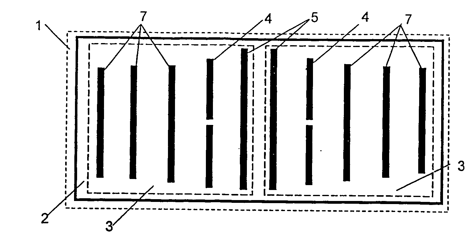
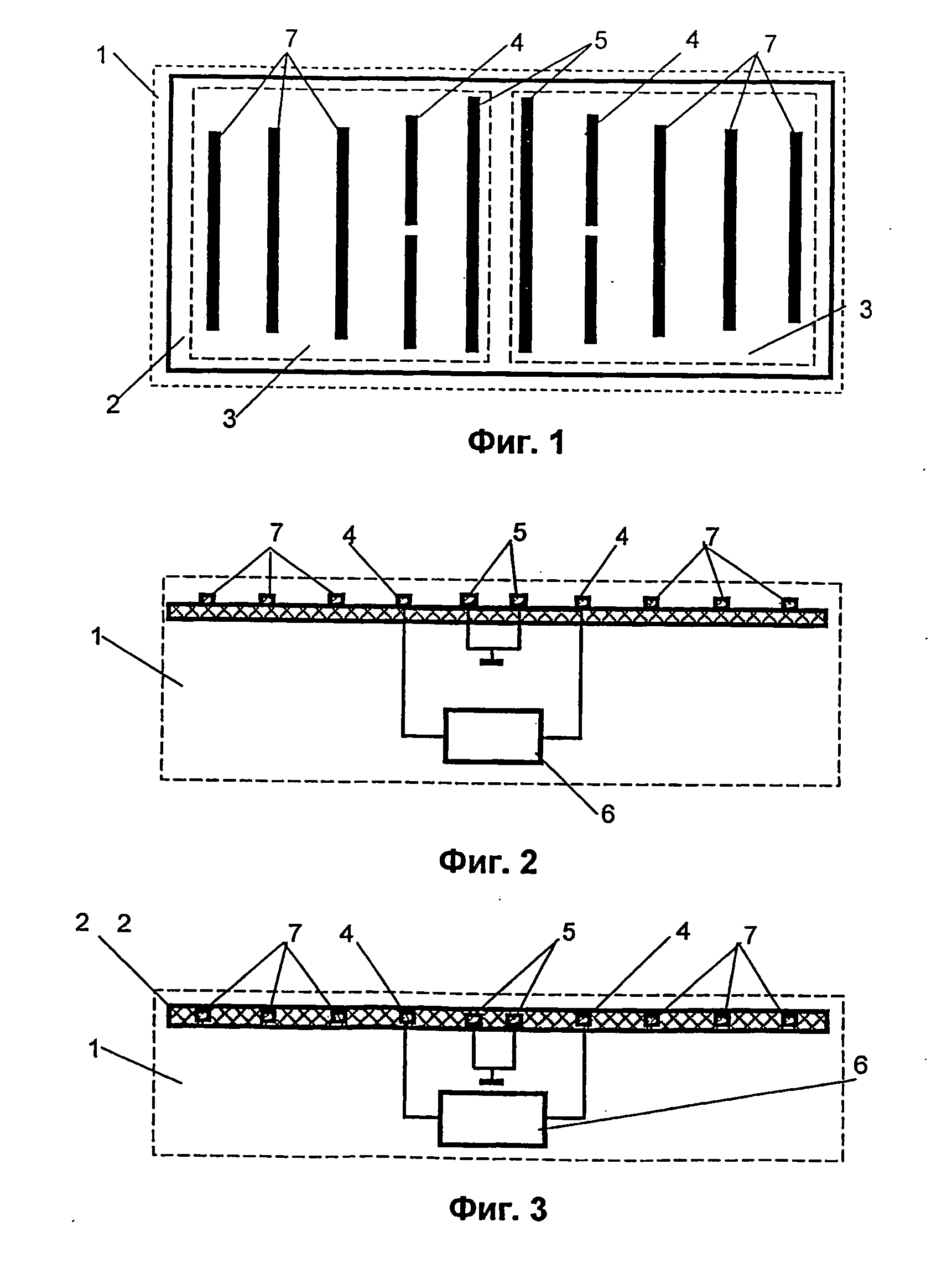
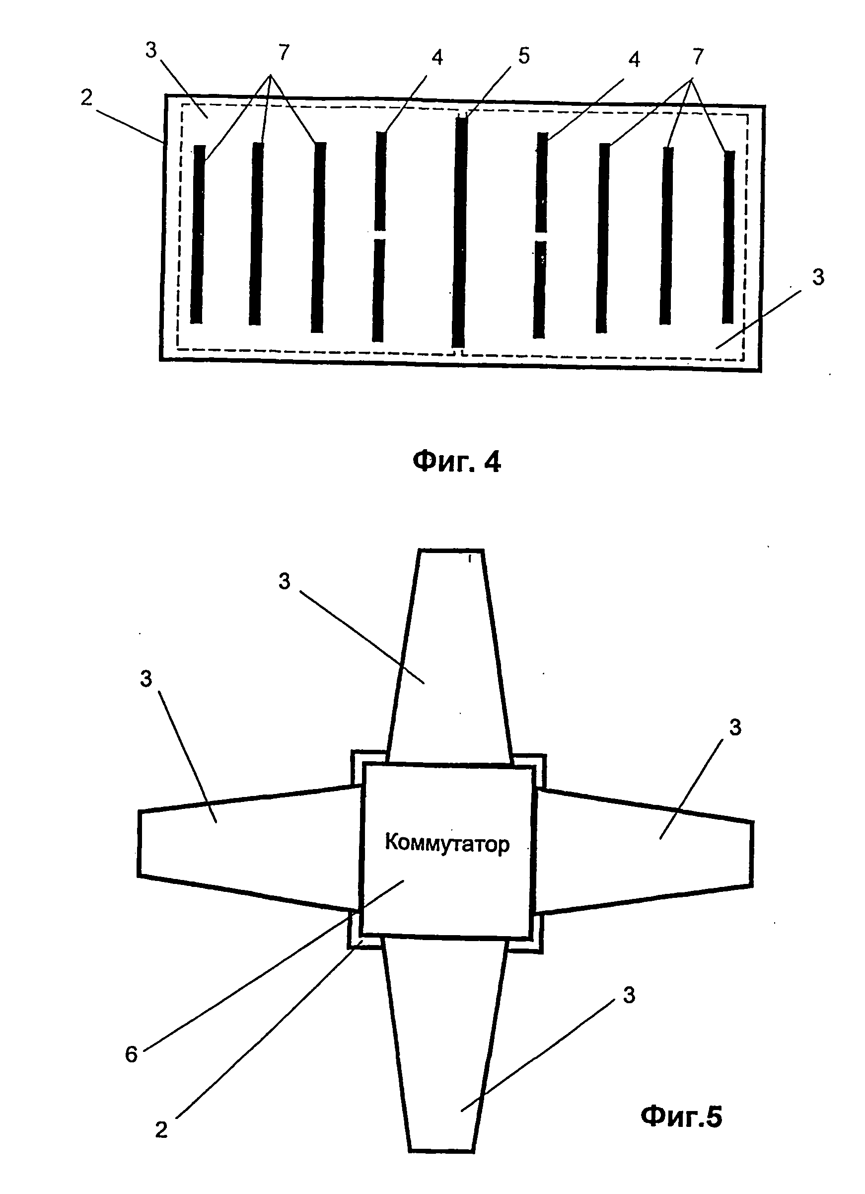
[0053] The claimed antenna system 1 in the simplest configuration includes substrate 2, on the surface of which two flat antennas 3 oriented in opposite directions are formed, for instance, by printing (see FIG. 1 and FIG. 2 where two Yagi antennas are shown as an example), consisting of active elements 4, reflectors 5. Active elements 4 are connected to commutation switch 6, controlling the directional pattern of antenna system 1 on the whole. Antennas 3 can be equipped with directors 7 to shape a narrow directional pattern of antennas 3. Antennas 3 can be located both on the surface of substrate 2 (see FIG. 2) and in the body of substrate 2 (see FIG. 3). To reduce the size of antenna system 1, antennas 3 may have a common reflector 5 (see FIG. 4).

[0054] Antenna system 1 may be made, for instance, as four dielectric antennas 3, oriented in a fan-like fashion (see FIG. 5), with commutation switch 6 placed between them. Commutation switch 6 can be equipped with a grounded case whose...


PUM


Abstract

The invention is related to antenna systems and transceiving equipment for network portable computers. The antenna system comprises a flat substrate (2), carrying at least two directional flat antennas oriented in a fan-like fashion (3), and a commutation switch (6) to control the directional pattern of the antenna system. The commutation switch is made so as to make it possible to switch on to one or two or more antennas simultaneously. The transceiving device comprises the antenna system (1), a reception/transmission switch (12), a transmitter (14), a receiver (16), an antenna system operation control unit (18) to control the operation of the antenna system in omnidirectional mode, directional scanning mode or stationary directional mode, and a controller (17). It can also be supplemented with a signal quality evaluation unit (20) and a signal identification unit (21). The network portable computer incorporates the transceiving device, the antenna system for which is fixed to the computer case by a hinge.

Description

FIELD OF THE INVENTION [0001] The claimed invention is related to antenna devices and transceiving equipment for transmission and reception of various types of data as used in portable network computers. BACKGROUND OF THE INVENTION [0002] Wireless Local Area Networks (WLAN) have presently found a still more extensive use in IT applications for transmission and distribution of data and other information between a multitude of users, for instance, between PCs and laptop computers located in one building without impairment to the mobility of such devices. When portable computers are to be used in such networks they are fitted with antenna systems of various types and different transceiving devices. Antenna systems for such computers should be small in size, lightweight, easy to manufacture, at the same time offering a broad functional range. [0003] An antenna system for portable computers is known, which consists of a substrate on one side of which two slot antennas are formed in the c...

Claims


Application Information

Patent Timeline
IPC IPC(8): H01Q19/10G06F1/16H01Q1/08H01Q1/22H01Q1/24H01Q1/38H01Q3/24H01Q13/10H01Q19/30H01Q21/28H01Q25/00H04B7/04H04B7/06H04B7/08
CPCG06F1/1616G06F1/1698H01Q1/084H01Q1/22H01Q1/2258H01Q1/2266H01Q1/24H01Q1/38H01Q3/24H01Q13/106H01Q19/30H01Q21/28H01Q25/00
Inventor ABRAMOV, OLEG Y.KASHKAROV, ALEXANDER G.NAGAAV, FARID I.
Owner AIRGAIN INC
Why Eureka
Try Eureka