
OLED display with aging compensation

Active Publication Date: 2007-05-10
GLOBAL OLED TECH
View PDF11 Cites 105 Cited by
  • Summary
  • Abstract
  • Description
  • Claims
  • Application Information

AI Technical Summary

Benefits of technology

[0015] The advantages of this invention include providing an OLED display device that compensates for the aging of the organic materials in the display without requiring extensive or complex circuitry, and having improved accuracy and / or speed of measurement.

Problems solved by technology

However, as the display is used, the organic materials in the device age and become less efficient at emitting light.
This reduces the lifetime of the display.
The differing organic materials may age at different rates, causing differential color aging and a display whose white point varies as the display is used.
If some light-emitting elements in the display are used more than other, spatially differentiated aging may result, causing portions of the display to be dimmer than other portions when driven with a similar signal.
This technique requires the measurement and accumulation of drive current applied to each pixel, requiring a stored memory that must be continuously updated as the display is used, requiring complex and extensive circuitry.
This design also requires pixel usage accumulation and the use of a calculation unit responsive to usage information for each pixel, greatly increasing the complexity of the circuit design.
This design presumes a predictable relative use of pixels and does not accommodate differences in actual usage of groups of pixels or of individual pixels.
Hence, correction for color or spatial groups is likely to be inaccurate over time.
While it is suggested that each group may consist of an individual light-emitting element, the current measurement of individual light-emitting elements is time-consuming and may be difficult and inaccurate because the current through each element is typically very small.
Alternatively, OLED systems that employ independent measurements of distinct groups of light-emitting elements over the entire OLED device are limited in their ability to deal with differential usage or light-emitter performance of individual elements within each group and cannot effectively compensate for such differential aging.

Method used


Image

  • OLED display with aging compensation
  • OLED display with aging compensation
  • OLED display with aging compensation

Examples


Embodiment Construction

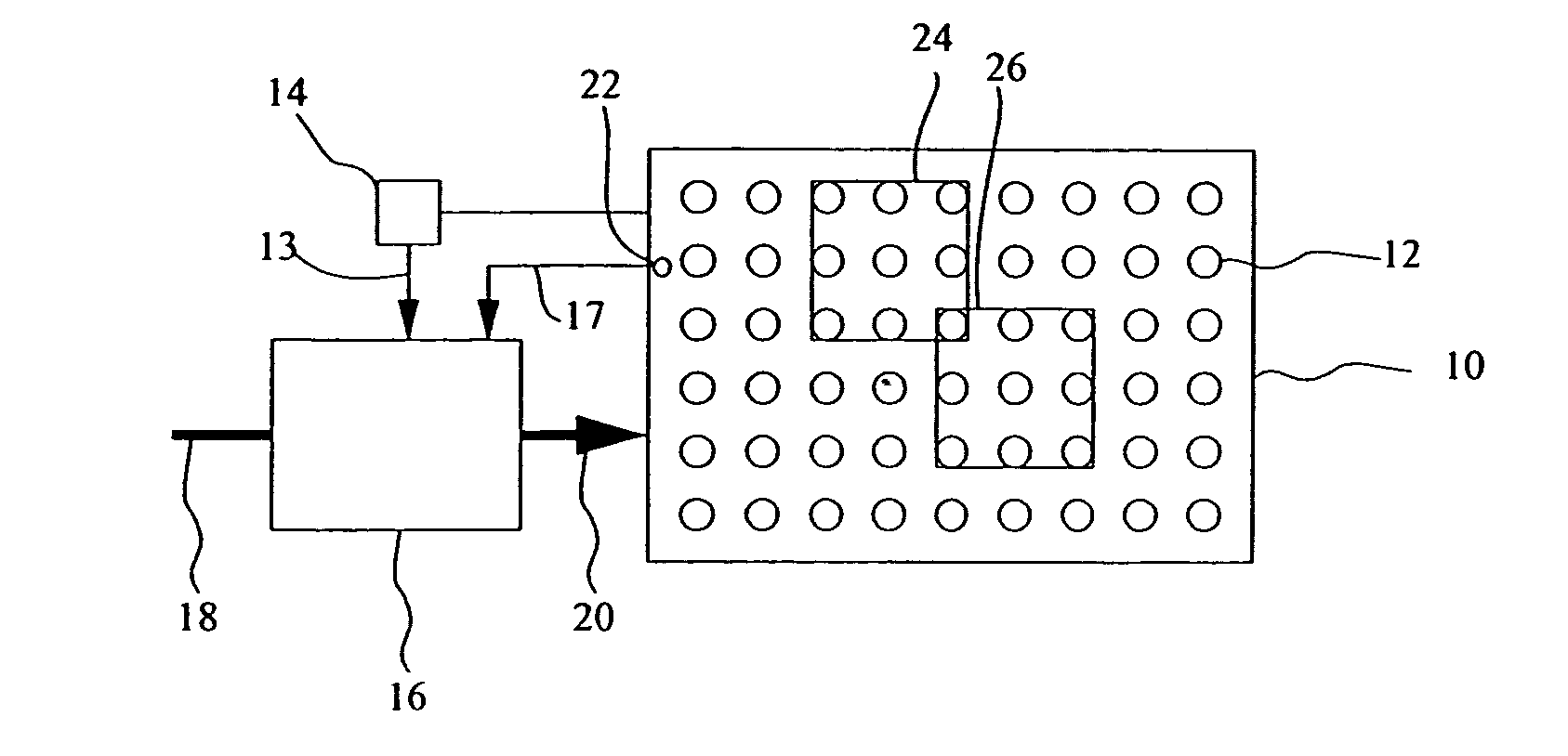
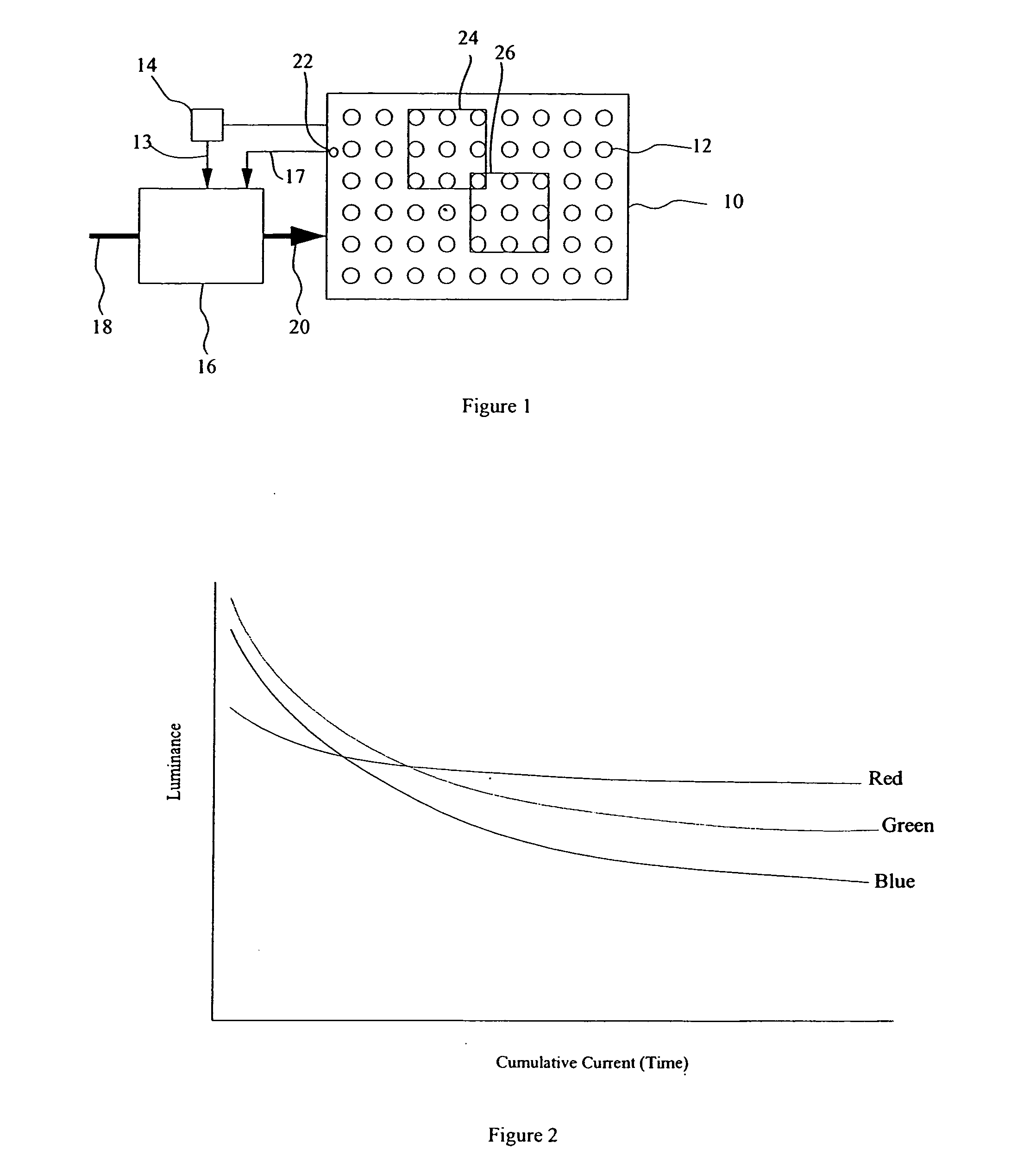
[0025] Referring to FIG. 1, an OLED display 10 system comprises a plurality of light-emitting elements 12 having outputs that change with time or use divided into two or more specified groups 24 and 26 wherein at least one light-emitting element is common to both groups 24 and 26. A current measuring device 14 senses the total current used by the display 10 at any given time when driven by a known image signal that causes the display 10 to illuminate the light-emitting elements 12 in one of the groups 24 or 26 to produce a total current signal 13. In a display calibration mode, controller 16 provides known image signals that activate all of the light-emitting elements 12 in each group 24 and 26. The controller 16 forms estimated values of current used by individual light-emitting elements in response to the total current signals 13, and stores at least one estimate of current used. By specifying groups containing at least one light-emitting element common to another specified group,...


PUM


Abstract

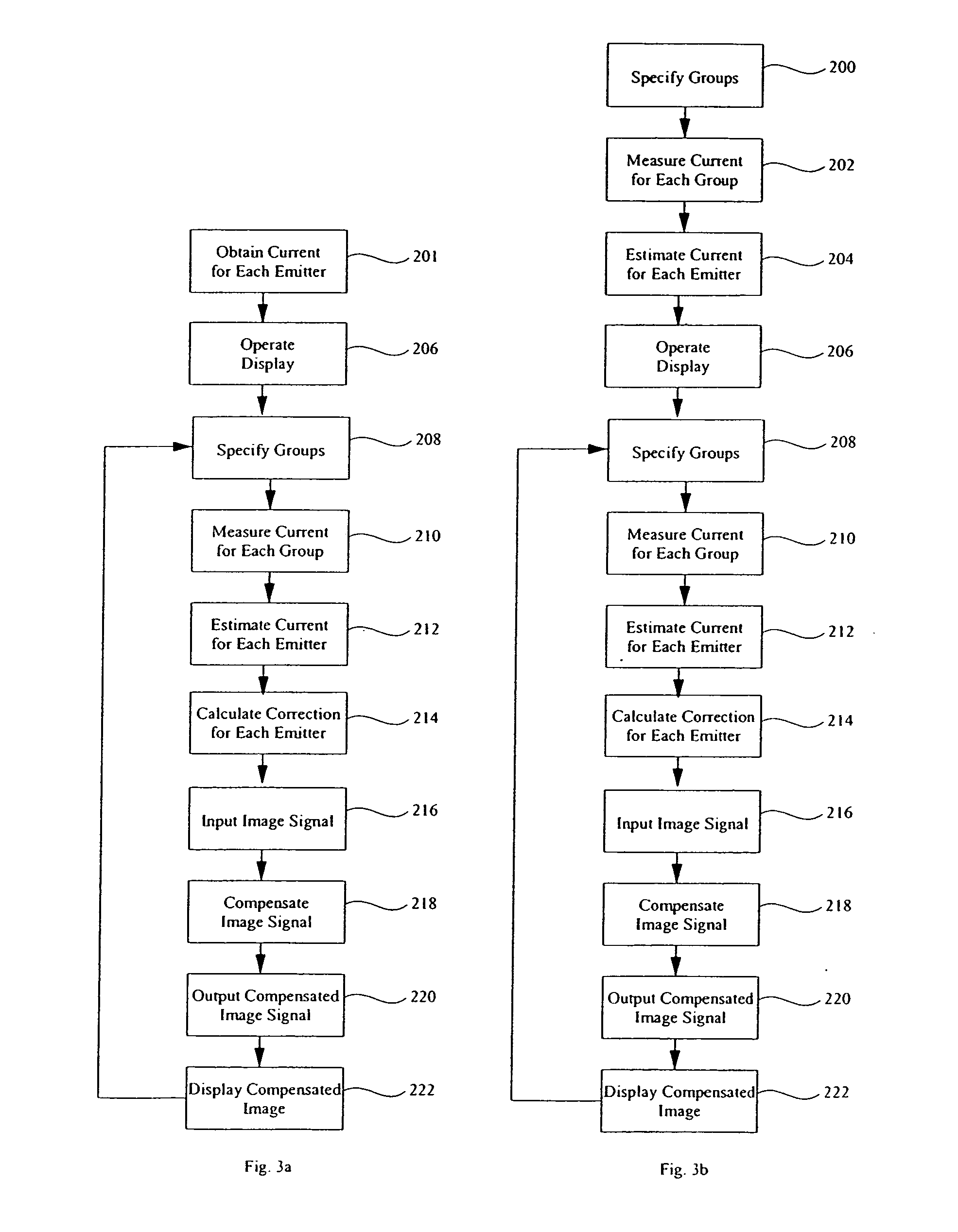
A method of compensating image signals for driving an OLED display having a plurality of light-emitting elements having outputs that change with time or use, comprising the steps of: a) obtaining a measured or estimated first value of the current used by individual light-emitting elements in response to known image signals at a first time; b) specifying multiple groups of light-emitting elements at a second time, wherein at least one of the specified groups contains at least one light-emitting element common to another specified group; c) measuring total currents used by each of the specified groups in response to known image signals at a second time; d) forming an estimated second value of the current used by individual light-emitting elements based on the measured total currents, e) calculating correction values for individual light-emitting elements based on the difference between the first and second current values, and f) employing the correction values to compensate image signals for the changes in the output of the light-emitting elements and produce compensated image signals.

Description

FIELD OF THE INVENTION [0001] The present invention relates to solid-state OLED flat-panel display devices and more particularly to such display devices having means to compensate for the aging of the organic light-emitting display. BACKGROUND OF THE INVENTION [0002] Solid-state organic light-emitting diode (OLED) image display devices are of great interest as a superior flat-panel display technology. These displays utilize current passing through thin films of organic material to generate light. The color of light emitted and the efficiency of the energy conversion from current to light are determined by the composition of the organic thin-film material. Different organic materials emit different colors of light. However, as the display is used, the organic materials in the device age and become less efficient at emitting light. This reduces the lifetime of the display. The differing organic materials may age at different rates, causing differential color aging and a display whose ...

Claims


Application Information

Patent Timeline
IPC IPC(8): G09G3/32H05B44/00
CPCG09G3/3216G09G3/3225G09G2320/0285G09G2320/0693G09G2320/041G09G2320/043G09G2320/029G09G2340/10H01L2924/12044Y02B20/30
Inventor COK, RONALD S.LEON, FELIPE A.
Owner GLOBAL OLED TECH
Learn More