Electrophoretic display module and electrophoretic display device

Active Publication Date: 2007-05-10
E INK CORPORATION
View PDF2 Cites 15 Cited by
  • Summary
  • Abstract
  • Description
  • Claims
  • Application Information

AI Technical Summary

Benefits of technology

[0008] An advantage of some aspects of the invention is to provide an electrophoretic display (EPD) module that does not apply a stress on an EPD laminate when the EPD laminat

Problems solved by technology

In the past, when the EPD laminate is fixed to a casing, since the EPD laminate is positioned and retained on the surface of the EPD unit on which EPD is performed, the positioning structure contacts the surface of the EPD unit, and a stress is applied to the contact portion to deteriorate th

Method used


Image

  • Electrophoretic display module and electrophoretic display device
  • Electrophoretic display module and electrophoretic display device
  • Electrophoretic display module and electrophoretic display device

Examples


Example

First Embodiment

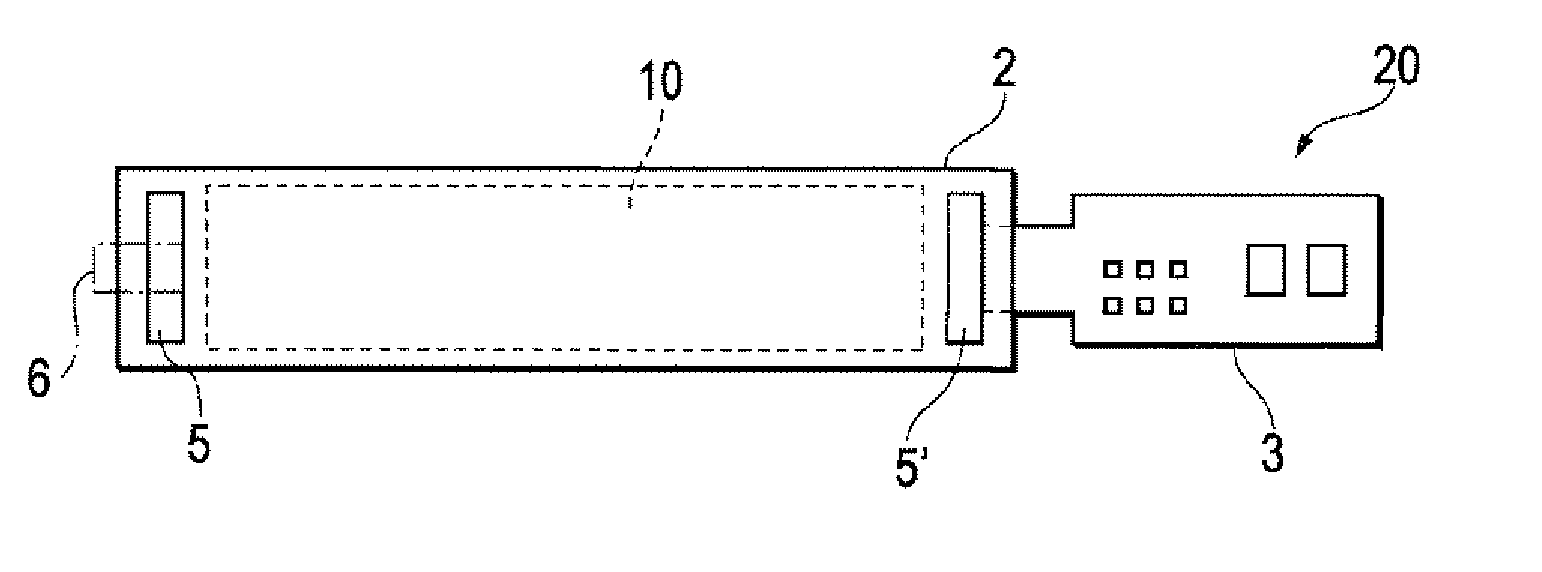
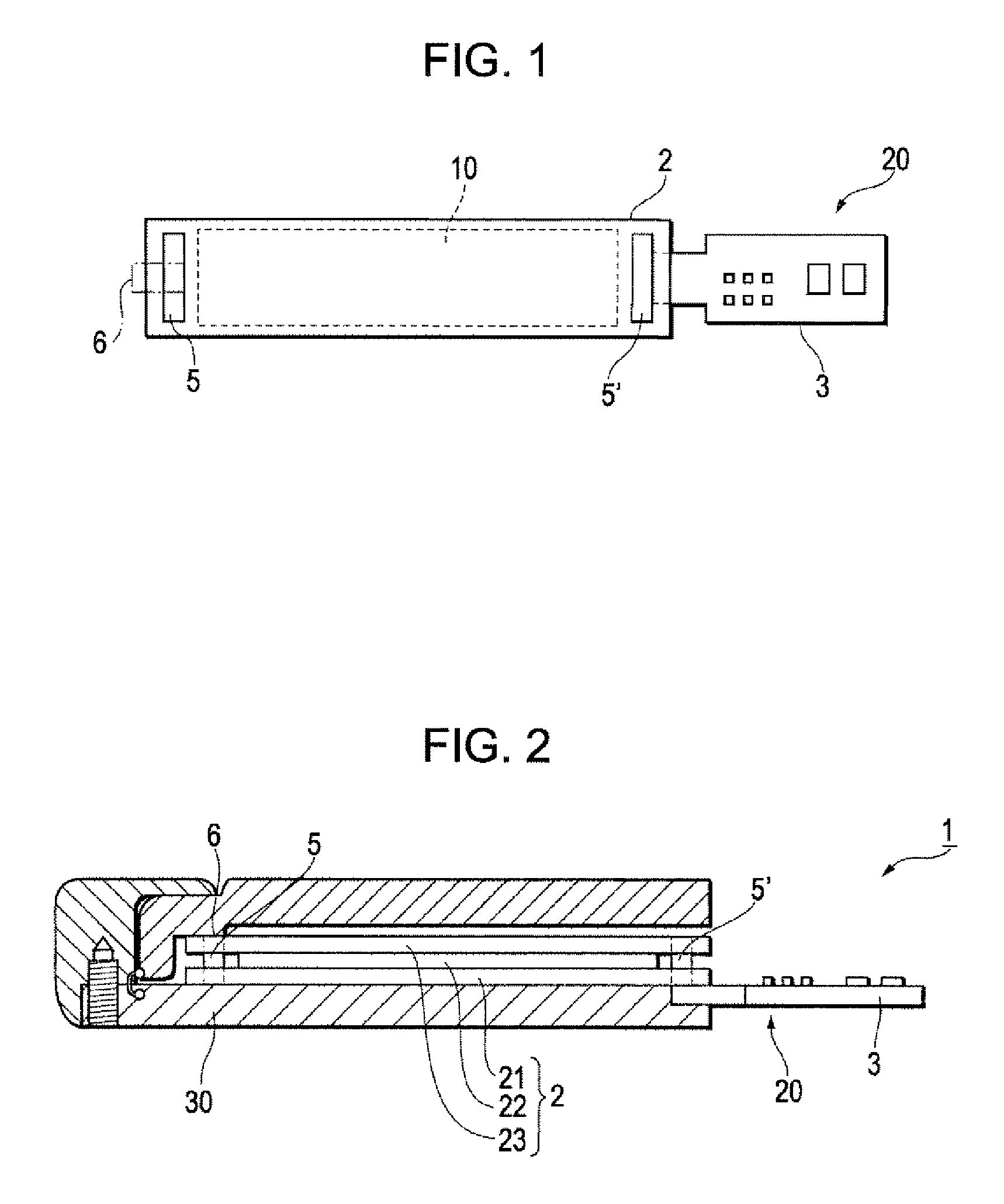
[0032]FIG. 1 is a top plan view of a wrist watch 20 used for an electrophoretic display (EPD) module according to the first embodiment. FIG. 2 is a side cross sectional view of the EPD module 1 in which the wrist watch 20 is mounted into a case 30.

[0033] As shown in FIG. 1, the wrist watch 20 includes an EPD laminate 2, conductive portions 5 and 5′ made of ITO layers which are located at both ends of the laminate 2, and a driving circuit unit 3. The laminate 2 includes an EPD unit 10.

[0034] As shown in FIG. 2, the EPD module 1 includes the wrist watch 20, the case 30 that encloses the wrist watch 20, and a retentive portion 6 that is located in the case 30. The driving circuit unit 3 is fixed to the laminate 2 by adhering to the conductive portion 5′.

[0035] The EPD laminate 2 includes a semiconductor substrate 21, a transparent electrode substrate 23, an EPD layer 22 located between the semiconductor substrate 21 and the transparent electrode substrate 23, and a ...

Example

Second Embodiment

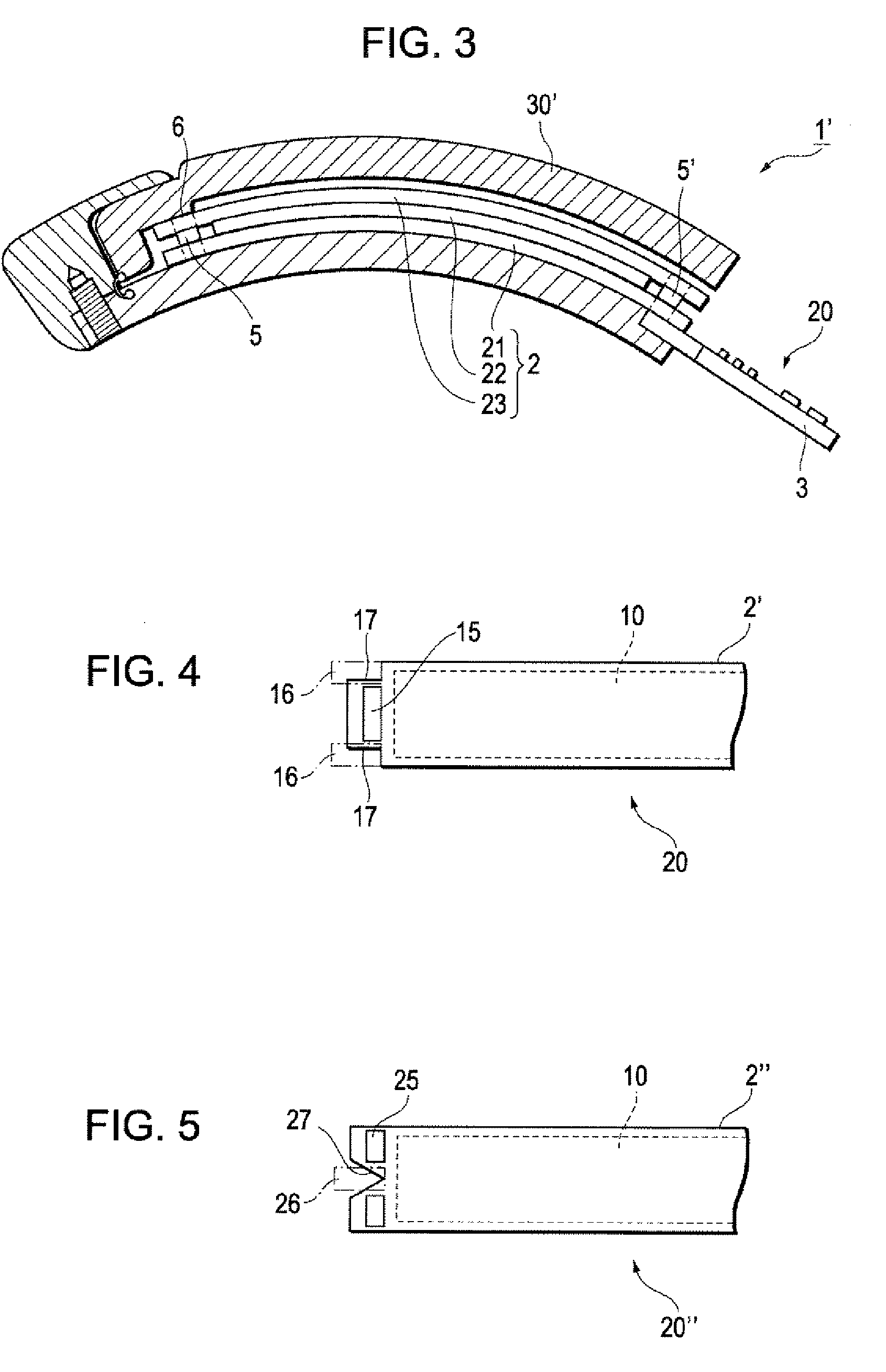
[0043]FIG. 3 is a side cross sectional view of the EPD module in which the wrist watch 20 is mounted into a case 30′ that has curved surfaces. Unlike the first embodiment, in the second embodiment, the case 30′ has a curved shape. In FIG. 3, the same elements as the elements of FIG. 1 are indicated by the same reference numerals, and the duplicated descriptions about the elements will be omitted.

[0044] As shown in FIG. 3, when the wrist watch 20 is mounted into the case 30′ that has the curved surfaces, the laminate 2 is incorporated in the case 30′ along the curved surfaces, and the retentive portion 6 contacts and retains the conductive portion 5 to position the laminate 2 with respect to the case 30′.

[0045] When the flexible laminate 2 is bent and mounted or fixed into the case 30′, a local stress due to elasticity of the laminate 2 is applied not to the surface of the EPD unit, but to the conductive portion 5. Accordingly, display anomaly is prevented, and th...

Example

Third Embodiment

[0046]FIG. 4 is a top plan view of a part of a wrist watch 20 used for an EPD module according to the third embodiment. Unlike the second embodiment, in the third embodiment, in the laminate 2′, the conductive portion 15 has two notch portions 17, and the retentive portions 16 retains the notch portions 17 to position the laminate 2′ with respect to the case.

[0047] As shown in FIG. 4, the two retentive portions 16 contact the notch portions 17 of the conductive portions 15, respectively, to position the laminate 2′ with respect to the case that has a curved shape.

[0048] Accordingly, in the embodiment, when the flexible laminate 2′ is bent and mounted or fixed into the case, a local stress due to electricity of the laminate 2′ is applied not to the surface of the EPD unit 10, but to the notch portions 17. Accordingly, display anomaly is prevented, and the reliability of a sealing portion is improved to obtain high display quality and electrical characteristics.


PUM


Abstract

An electrophoretic display (EPD) module includes an EPD laminate, conductive portions made of ITO layers which are located at both ends of the EPD laminate, a casing that encloses the EPD laminate, and retentive portions that are provided in the casing and retain the EPD laminate, in which the retentive portions contact and retain at least a part of the conductive portions to position the EPD laminate with respect to the casing.

Description

BACKGROUND [0001] 1. Technical Field [0002] The present invention relates to an electrophoretic display module that employs an electrophoresis phenomenon, in which charged particles are moved by an applied voltage, for forming images, or an electrophoretic display device that employs the electrophoretic display module, and more particularly, to an electrophoretic display module having a specific structure, in which an electrophoretic laminate is fixed to a casing, and an electrophoretic display device that employs the electrophoretic display module. [0003] 2. Related Art [0004] An electrophoretic display (EPD) device includes an electrophoretic laminate that employs an electrophoresis phenomenon in which particles dispersed in a solvent are moved by an applied voltage. The EPD may employ a microcapsule type electrophoretic method, a horizontal movement type electrophoretic method, a vertical movement type electrophoretic method or the like. The EPD device can be easily fabricated or...

Claims


Application Information

Patent Timeline
IPC IPC(8): G09G3/34G02F1/167G02F1/16753
CPCG02F1/1345G02F1/167G02F1/16753G02F1/1676
Inventor TAKEI, YOSHIKI
Owner E INK CORPORATION
Why Eureka
Try Eureka