

Projector
a projector and projector technology, applied in the field of projectors, can solve the problems of variable emission spectrum, inability to discharge, and predetermined amount of time to obtain the necessary amount of ligh
- Summary
- Abstract
- Description
- Claims
- Application Information
AI Technical Summary
Benefits of technology
Problems solved by technology
Method used
Image

Examples
first embodiment
(First Embodiment)
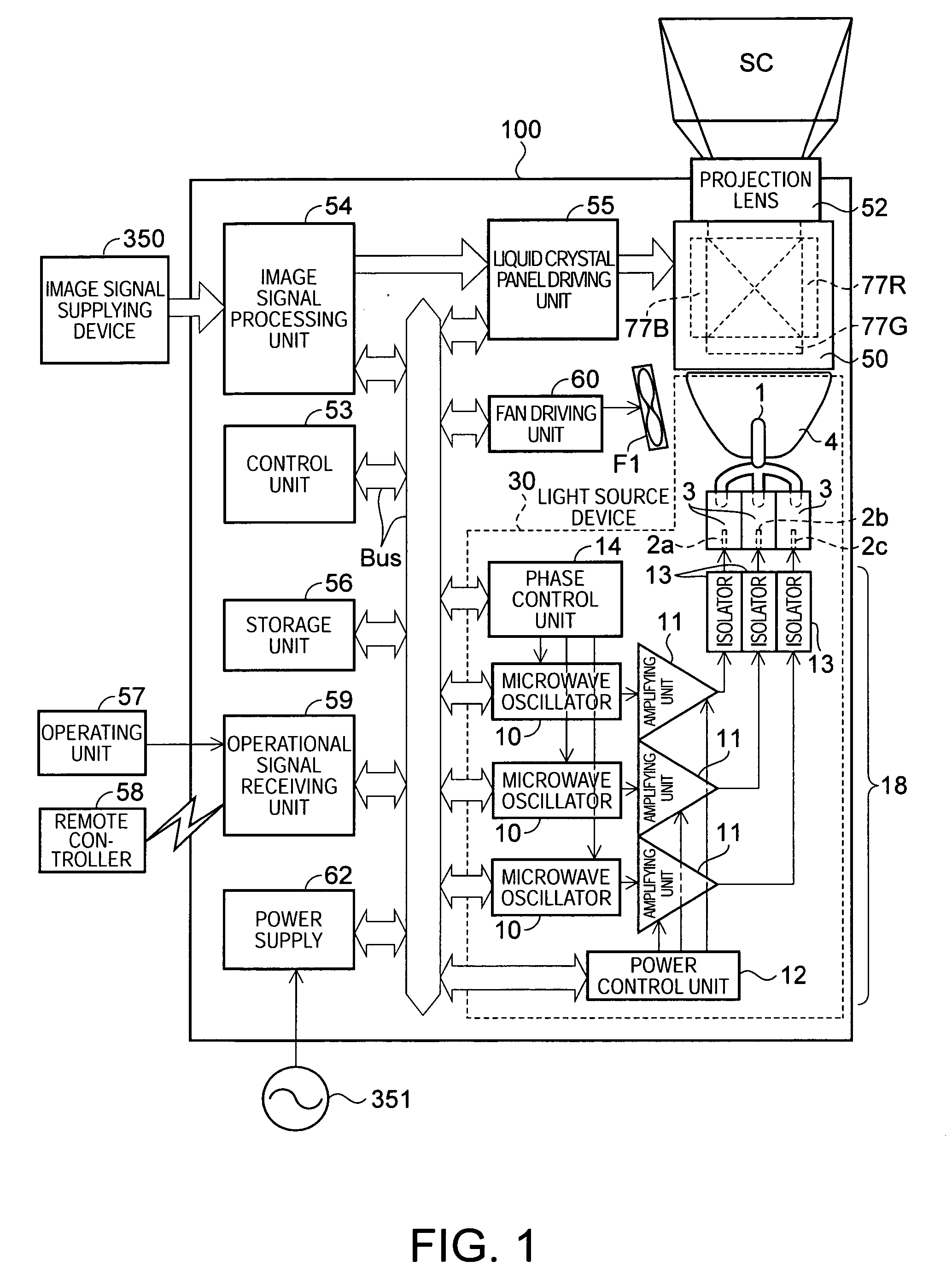
[0042]FIG. 1 is a diagram schematically illustrating the structure of a projector according to a first embodiment of the invention.
[0043] A projector 100 is a so-called projector of a three liquid crystal panel type in which light emitted from a light source device 30 is separated into three color light components, that is, red, green, and blue light components, the separated light components are modulated by red, green, and blue liquid crystal light valves 77R, 77G, and 77B, serving as light modulating devices, according to image signals, the modulated light components are combined into a full color optical image, and the full color optical image is enlarged and projected onto a screen SC by a projection lens 52. The liquid crystal light valves 77R, 77G, and 77B are provided for the red, green, and blue light components, respectively, and are included in the structure of an optical unit 50.
[0044] In the light source device 30, an electrodeless lamp 1, serving as...
second embodiment
(Second Embodiment)
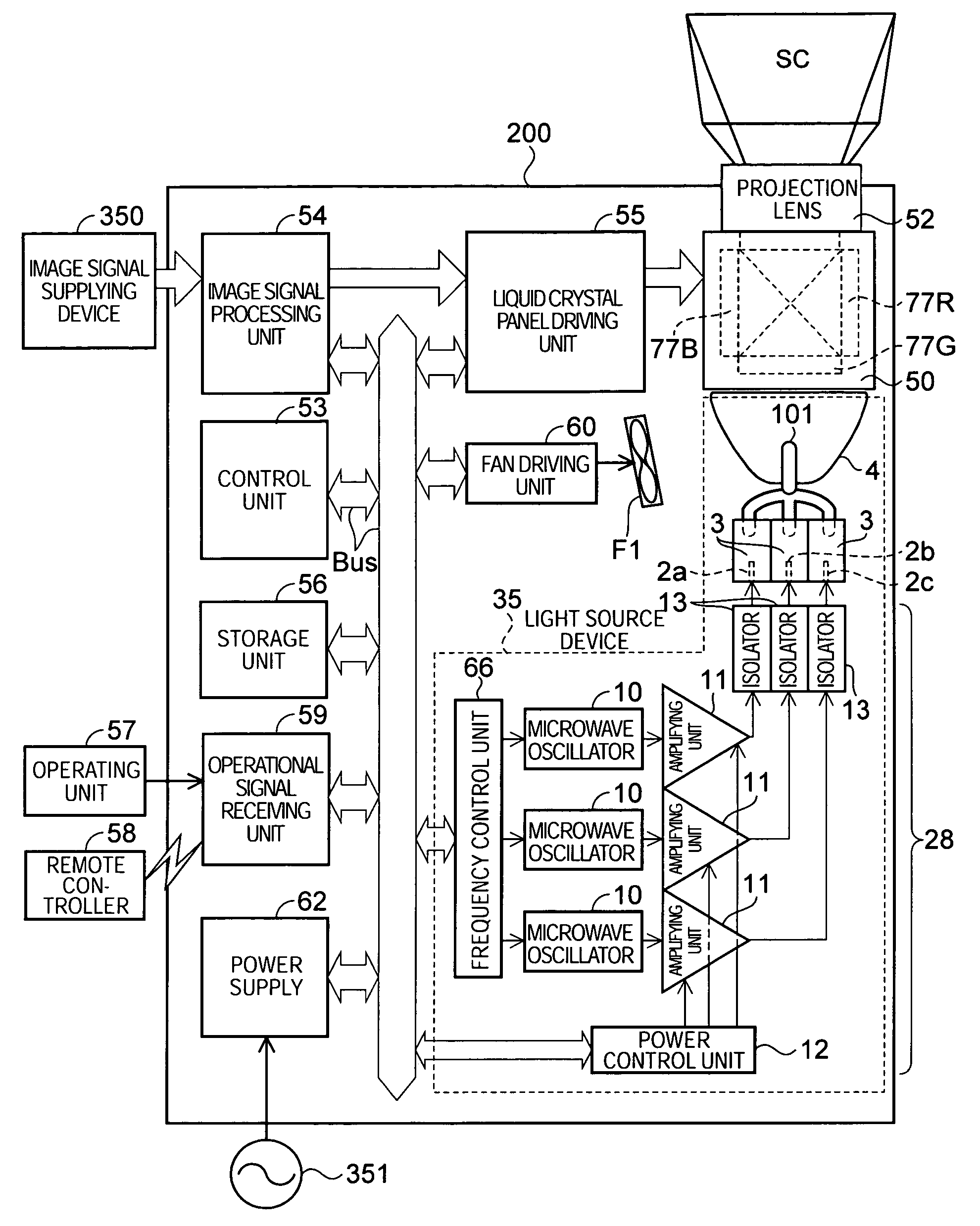
[0177]FIG. 9 is a diagram schematically illustrating the structure of a projector according to a second embodiment of the invention.
[0178] A projector 200 according to the second embodiment is similar to the projector 100 according to the first embodiment except for the following three points.
[0179] First, an electrodeless lamp 101 of the projector 200 has a different structure from that of the electrodeless lamp 1 (FIG. 5).
[0180] Second, instead of the phase control unit 14 (FIG. 1), a frequency control unit 66 is provided in a light source device 35 of the projector 200.
[0181] Third, a storage unit 56 of the projector 200 stores programs, and some of the programs are different from those in the projector 100.
[0182] In the second embodiment, the same components as those in the projector 100 according to the first embodiment have the same reference numerals, and the schematic structure of the projector 200 will be described, centered on the above-mentioned th...
third embodiment
(Third Embodiment)
[0252]FIG. 12 is a diagram schematically illustrating the structure of a projector according to a third embodiment of the invention.
[0253] The schematic structure of a projector 300 that uses a tilt mirror device as a light modulating device and the light source device 35 according to the second embodiment as a light source will be described with reference to FIGS. 8, 9, and 12.
[0254] In this embodiment, the same components as those in the first and second embodiments have the same reference numerals, and a detailed description thereof will be omitted.
[0255] The projector 300 uses a digital micromirror device (DMD; made by Texas Instruments Inc.), which is a single tilt mirror device, as a light modulating device.
[0256] The projector 300 includes a light source device 35, a first lens array 111, a second lens array 112, a superimposing lens 114, a DMD 301, and a projection lens 52.
[0257] Light emitted from the light source device 35 passes through the first le...
PUM
 Abstract
Description
Claims
Application Information