Configuration recognizing system, configuration recognizing method, and configuration recognizing program of device

a configuration recognition and configuration technology, applied in the field of configuration recognition system, configuration recognition method, and configuration recognition program, can solve the problems of troublesome maintenance and replacement operations, mounting apparatus does not recognize the substrate, and does not allow the device to recognize, so as to improve the efficiency of maintenance work, reduce costs, and acquire configuration information easier

Inactive Publication Date: 2007-05-10
FUJITSU LTD
View PDF7 Cites 18 Cited by
  • Summary
  • Abstract
  • Description
  • Claims
  • Application Information

AI Technical Summary

Benefits of technology

[0036] As described above, the present invention relates to a component mounted to a device and enables configuration information to be comprehended regardless of electric connection between the component and the device without contact with the component.
[0037] According to the present invention, the comprehended configuration information can be utilized for management of the component, such as determining whether the component is suitable and selecting the recommended component. For example, the alteration due to increase in the substrate information such as IDs of the components can be suppressed to achieve cost reduction and, since the configuration information can be comprehended without the need for electric connection with the component or power supply, this can make the configuration information acquired easier and improve the efficiency of the maintenance work.
[0038] A database is made for the configuration information after change in the configuration such as replacement of the component, which contributes to the elaborate component management.

Problems solved by technology

Since the memory capacity of the unit often cannot be recognized unless supplying electric power (powering on) to the system substrate and the determination cannot be made for the memory configuration violation and the number of licenses corresponding to the memory configuration before supplying electric power, the maintenance and replacement operations are troublesome.
That is, the mounting apparatus does not recognize the substrate mounted thereto.
The system and method do not allow a device to recognize a component mounted to the device to perform a process corresponding to the component.

Method used


Image

  • Configuration recognizing system, configuration recognizing method, and configuration recognizing program of device
  • Configuration recognizing system, configuration recognizing method, and configuration recognizing program of device
  • Configuration recognizing system, configuration recognizing method, and configuration recognizing program of device

Examples


first embodiment

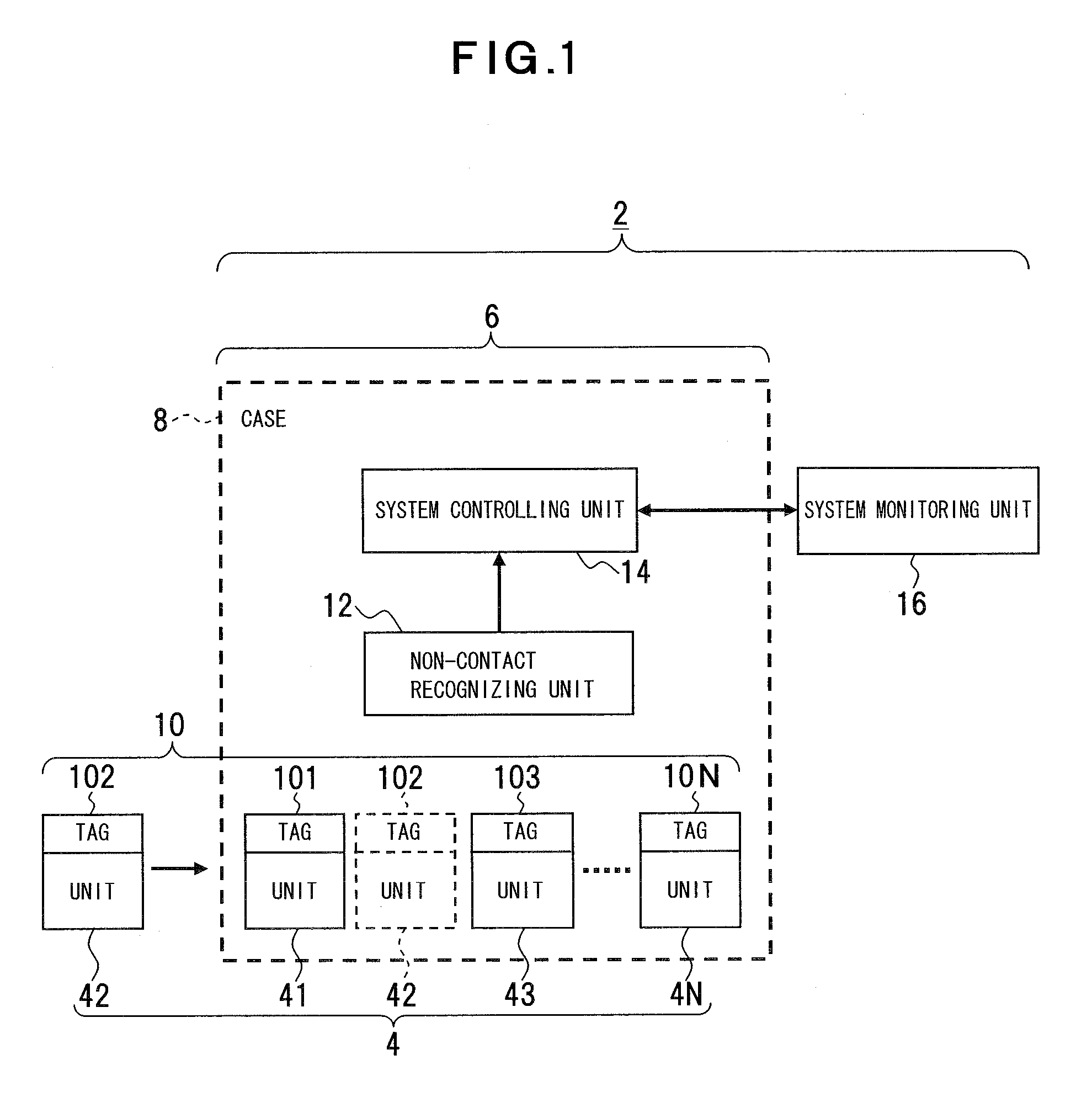
[0060] A first embodiment of the present invention, i.e., a configuration recognizing system for an electronic device will be described with reference to FIG. 1. FIG. 1 is a block diagram of an outline of a configuration recognizing system for an electronic device.

[0061] This configuration recognizing system 2 establishes automated recognition of a component 4 without intervention of electric connection. The configuration recognizing system 2 according to this embodiment is directed to an electronic device 6 such as a server apparatus; inside a case 8 of the electronic device 6, the component 4 is included which is a plurality of replaceable units 41, 42, 43 . . . 4N such as a substrate unit, CPU (Central Processing Unit), and memory, for example; and the units 41, 42, 43 . . . 4N are disposed with a plurality of tags 101, 102, 103 . . . 10N, which are a tag 10 configuring a displaying unit that individually displays configuration information. Each tag 101, 102, 103 . . . 10N displ...

second embodiment

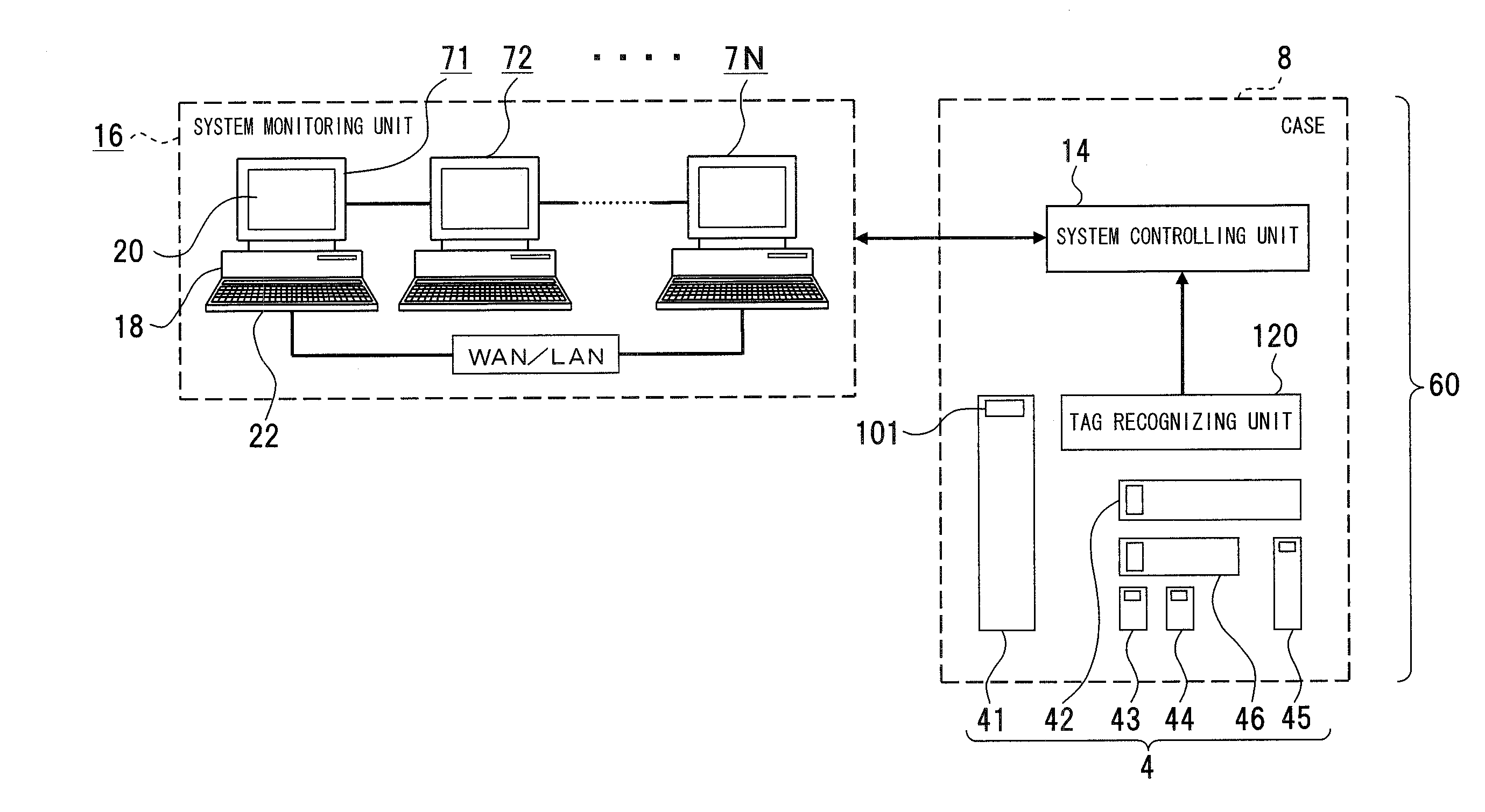
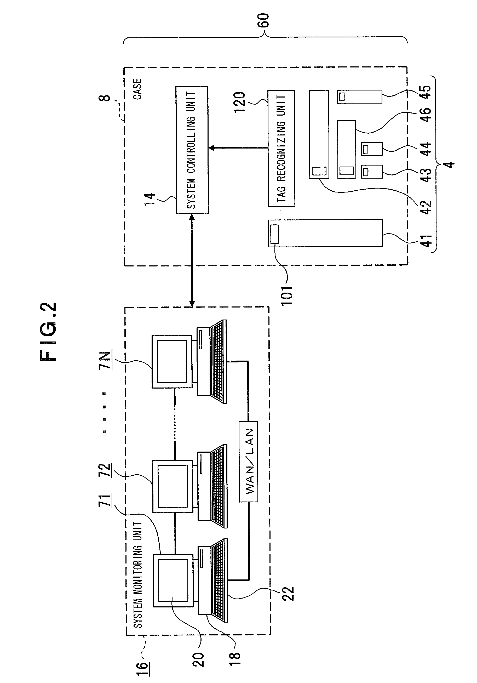
[0067] A second embodiment of the present invention, i.e., a configuration recognizing system for a server apparatus will be described with reference to FIG. 2. FIG. 2 is a block diagram of an outline of a configuration recognizing system for a server apparatus. The same reference numerals are added to the same portions as the first embodiment.

[0068] In the configuration recognizing system 2 of the embodiment, a server apparatus 60 is disposed as a target device of configuration recognition and the server apparatus 60 corresponds to the electronic device 6 (FIG. 1) of the first embodiment. A case 8 of the server apparatus 60 includes a plurality of replaceable units 41, 42, 43 . . . 4N as the component 4. The units 41, 42, 43 . . . 4N are control substrates, memories, etc. The above tags 101, 102, 103 . . . 10N are attached to the units 41, 42, 43 . . . 4N. As described above, the barcode labels, IC (Integrated Circuit) tags, magnetic stripe labels, image recognition labels, etc., ...

third embodiment

[0072] A third embodiment of the present invention, i.e., a configuration recognizing method and recognizing program for a device will be described with reference to FIG. 4. FIG. 4 is a flowchart of a process of each procedure of the configuration recognizing method and each step of the configuration recognizing program in the configuration recognizing system of a server apparatus.

[0073] The tags 101, 102, 103 . . . 10N are independently added to the units 41, 42, 43 . . . 4N mounted to the server apparatus 60. That is, the tags 101, 102, 103 . . . 10N represent the distinction information, characteristic values, editions, versions, manufacturers, model numbers, serial numbers, applications, maintenance information, etc., of the units 41, 42, 43 . . . 4N.

[0074] The mounting or replacement target units 41, 42, 43 . . . 4N are mounted to the case 8 of the server apparatus 60 (step S1) the tag recognizing unit 120 recognizes the tags 101, 102, 103 . . . 10N of the mounted units 41, 4...


PUM


Abstract

The present invention relates to a component mounted to a device and provides a configuration recognizing system, etc. of a device to enable configuration information of the component to be comprehended regardless of electric connection between the component and the device. A configuration recognizing system of a device (electronic device 6, server apparatus 60) with one or a plurality of components (units 41, 42, 43 . . . 4N) mounted includes a displaying unit (tag 101, 102, 103 . . . 10N) that displays configuration information on the component and a recognizing unit (non-contact recognizing unit 12) that recognize the configuration information from the displaying unit of the component mounted to the inside of the case without contact.

Description

CROSS-REFERENCE TO RELATED APPLICATIONS [0001] This application is a continuation of International Application No. PCT / JP2004 / 011082, filed on Aug. 03, 2004, now pending, herein incorporated by reference.BACKGROUND OF THE INVENTION [0002] 1. Field of the Invention [0003] The present invention relates to a configuration recognizing system, configuration recognizing method, and a configuration recognizing program for recognizing a component such as a unit mounted to various devices such as server systems on the device side without intervention of electric connections. [0004] 2. Description of the Related Art [0005] Although units such as CPUs and memories are mounted to various server systems such as a communication server, database server, and file server, each unit includes unique information such as a unit ID and the unique information is displayed with a pattern embedded in a unit substrate. When each unit is mounted to a case and electric connection is established, the unique inf...

Claims


Application Information

Patent Timeline
Patent Type & Authority Applications(United States)
IPC IPC(8): G06F3/12G06F3/08G06F11/30G06K17/00
CPCG06Q10/06
Inventor KAWAHARA, JUNMURAKAMI, HIROSHI
Owner FUJITSU LTD
Why Eureka
Try Eureka