Chassis with positive pressure

Inactive Publication Date: 2007-05-10
STEELCLOUD
View PDF63 Cites 1 Cited by
  • Summary
  • Abstract
  • Description
  • Claims
  • Application Information

AI Technical Summary

Benefits of technology

[0008] Embodiments of the invention address deficiencies of the art in respect to an electronic system chassis and provide a novel and non-obvious device for reducing the amount of particulate-laden air entering the chassis of the electronic system. In this regard, the chassis for an electronic device, such as a computer, includes a plurality of fans attached to a single face of the chassis with each of the fans directing a fluid into an interior of the chassi

Problems solved by technology

Electronic systems, such as computers, are vulnerable to particulate matter.
Additionally, particulate matter can build up on cooling devices, such as a heat sink, which decreases the efficiency of the cooling device.
The use of a clean room environment, however, is not feasible in many applications.
For example, in a situation where a computer is used to control equipment on a factory floor, placing the computer in a clean room creates issues associated with connecting the computer to the equipment as well as easily accessing the computer while operating the equipment.
Although a common technique has been to place filters over the cooling fans, in most instances, there are many opening in the computer chassis, besides the location of the cooling fan, where particulate matter can enter the chassis.
This solution, however, is not commonly adopted since the solution is often too expensive to be practicable.
Furthermore, maintaining the integrity of any seals within the computer chassis can also be expensive.

Method used


Image

  • Chassis with positive pressure
  • Chassis with positive pressure
  • Chassis with positive pressure

Examples


example

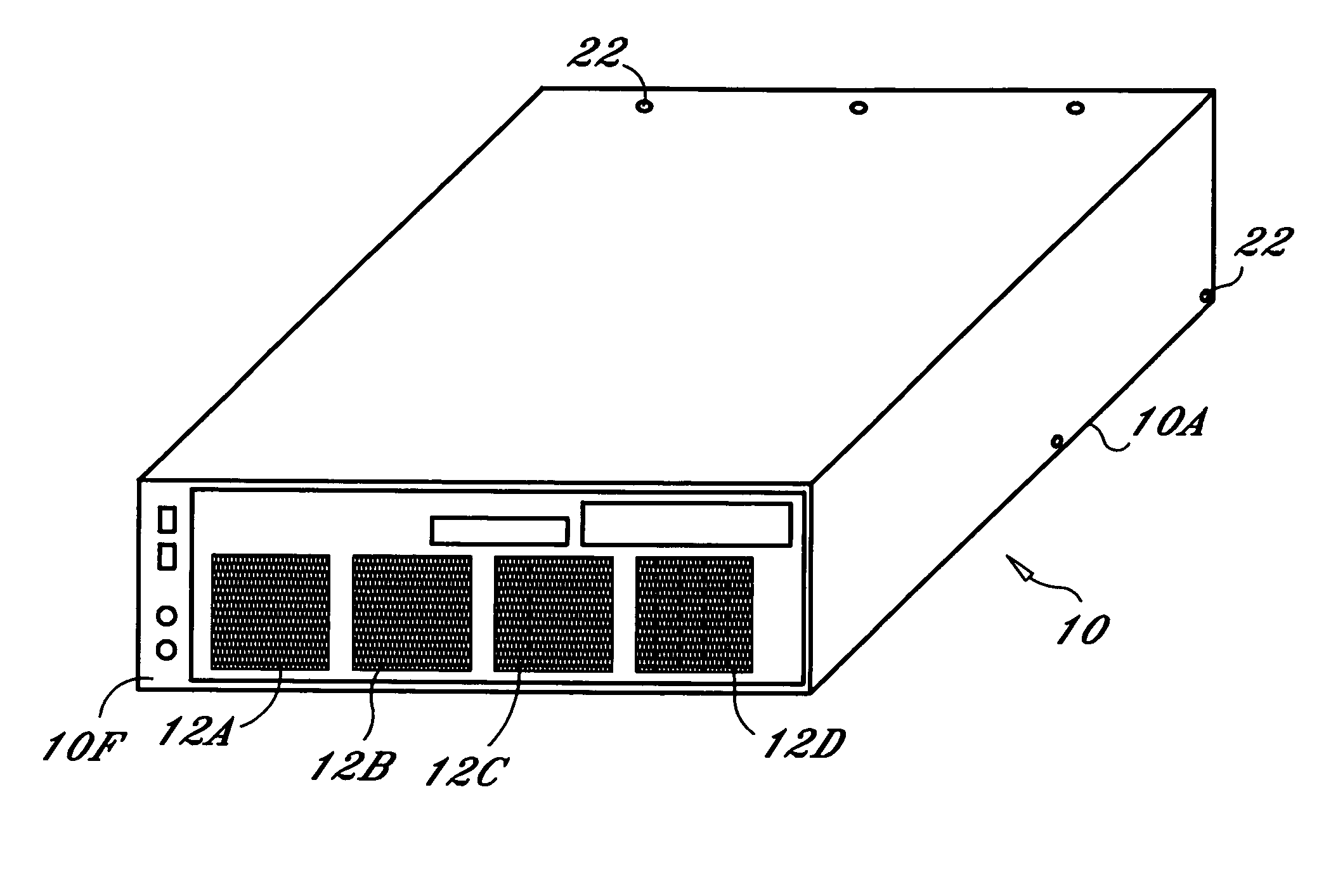
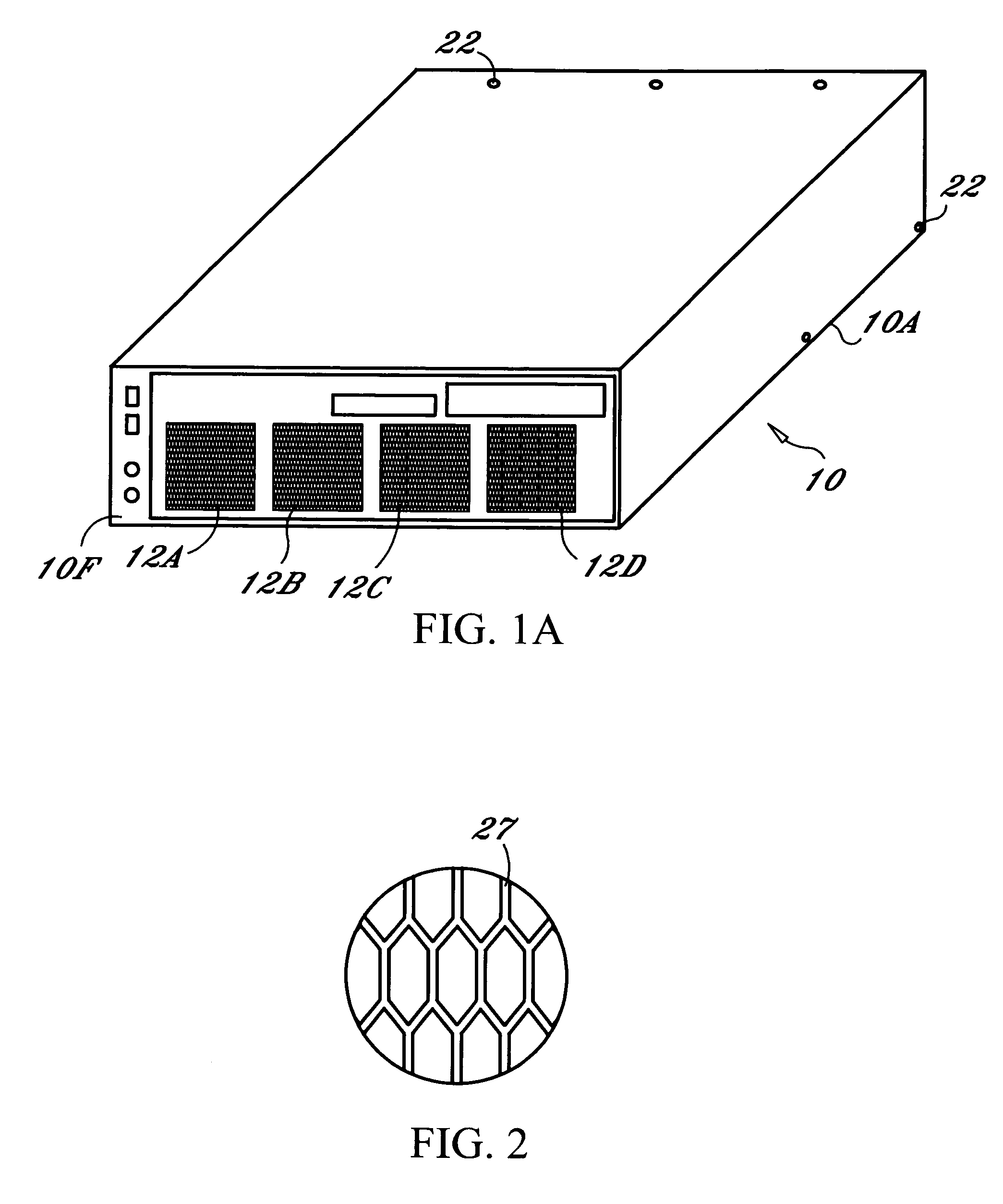
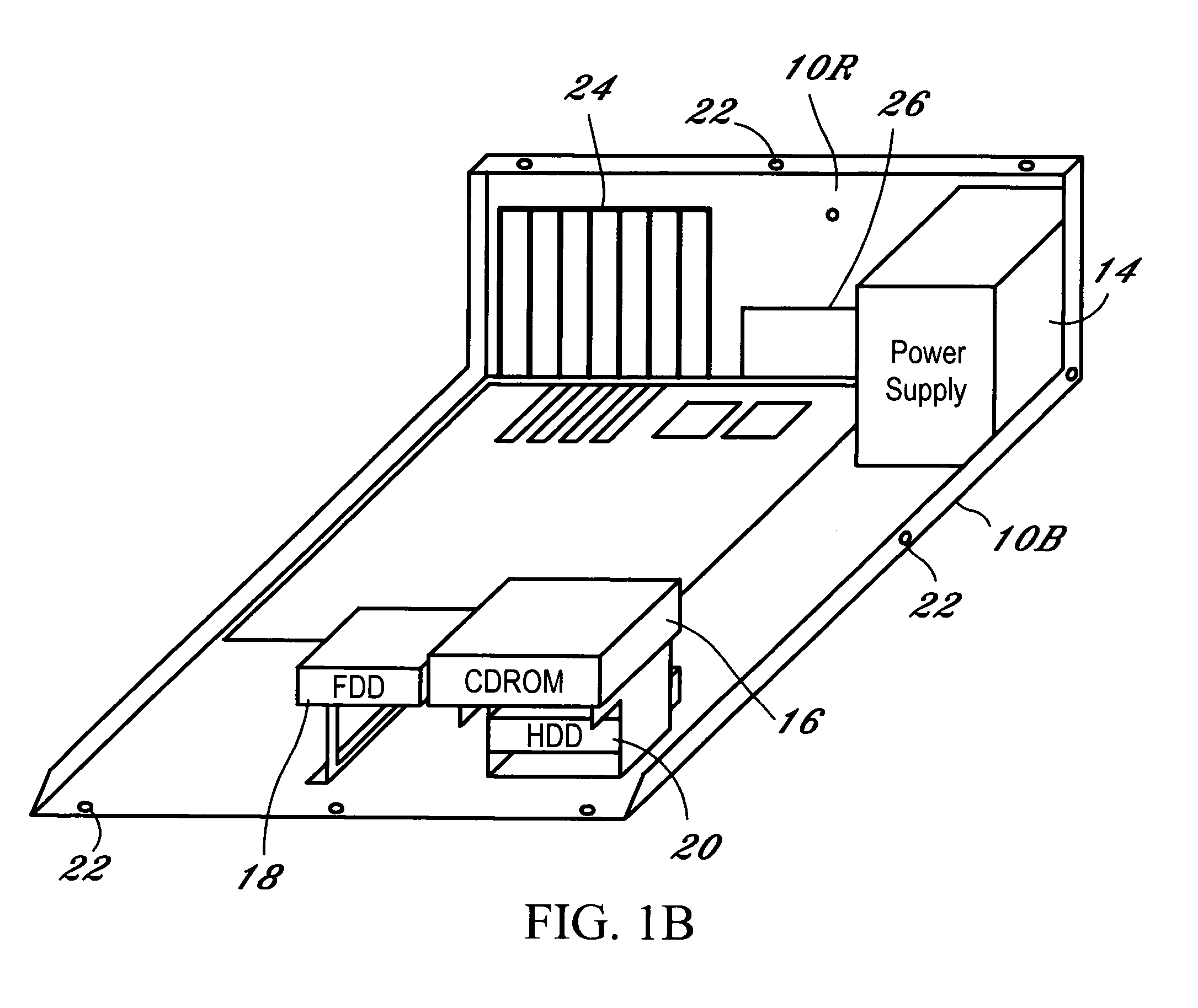
[0028] The chassis has a height of 6.25″, a depth of 16.25″, and a width of 17,″ which yields an internal volume of approximately 1 ft3 and a total area bounded by the chassis 10 as 2×((6.25″×16.25″)+(6.25″×17″)+(16.25″×17″)) or 968 in2. The area of the output openings of the chassis were determined to be approximately 17.2 in2, which is broken down into 509 holes in a rear bezel for 9.72 in2, a slot cover of 0.36 in2, 4 rack mount screw holes for 0.057 in2, and 7.065 in2 for a power supply exhaust opening. The percentage of an area (17.2 in2) of all the output openings to the total area (968 in2) bounded by the chassis 10 is 1.8%.

[0029] The area of the input openings of the chassis is determined to be approximately 17.73 in2, which is broken down into 3 cooling fans having a 3″ diameter with a hexagon bezel covering 16% of the opening. This yields a percentage of an area of the fans on the face to total area of the face of (3*π*(1.5″)2) to (6.25″*17″) or approximately 20.0%. The v...


PUM


Abstract

A chassis for an electronic device, such as a computer, includes a plurality of fans attached to a single face of the chassis with each of the fans directing a fluid into an interior of the chassis and towards a second face of the chassis. The second face of the chassis has a greatest total area of output of openings within the chassis, and a positive pressure exists between the interior of the chassis and an exterior of the chassis at all the output openings within the chassis. At least one detachable filter is disposed over the plurality of fans, and at least one hexagon-shaped bezel is disposed between the plurality of fans and the at least one filter.

Description

BACKGROUND OF THE INVENTION [0001] 1. Field of the Invention [0002] The disclosure relates generally to a chassis for an electronic system and, more specifically, to a computer chassis for use in a dirty environment. [0003] 2. Description of the Related Art [0004] Electronic systems, such as computers, are vulnerable to particulate matter. For example, particulate matter can prevent hard drives and / or optical drives from properly reading media. Additionally, particulate matter can build up on cooling devices, such as a heat sink, which decreases the efficiency of the cooling device. Issues related to particulate matter, however, do not arise often in relatively clean environments, such as a typical office or home. Furthermore, where uptime of the electronic system is of particular importance, one manner of addressing these issues has been to place the electronic system in a clean room. [0005] The use of a clean room environment, however, is not feasible in many applications. For exa...

Claims


Application Information

Patent Timeline
IPC IPC(8): H05K7/20
CPCG06F1/20
Inventor COSTELLO, DAVIDPERRI, MICHAEL
Owner STEELCLOUD
Why Eureka
Try Eureka