Hole saw having a drill bit with a pilot tip

Active Publication Date: 2007-05-10
BLACK & DECKER INC
18 Cites 7 Cited by

AI-Extracted Technical Summary

Problems solved by technology

A common problem which exists with these dril...

Benefits of technology

[0004] The present invention provides the art with a hole saw which reduces the time required to drill a hole into the workpiece. Also, the present invention provides a ...

Abstract

A hole saw has an arbor and a cup shaped cutting member. The cup shaped cutting member has an annular skirt with a plurality of teeth at its free end. A drill bit is secured on the arbor. The drill bit includes a pilot point with a first cutting edge. A second edge is formed on the body portion of the drill bit to form a constant diameter hole in the workpiece.

Application Domain

Wood turning toolsTransportation and packaging +5

Technology Topic

EngineeringDrill bit +2

Image

  • Hole saw having a drill bit with a pilot tip
  • Hole saw having a drill bit with a pilot tip
  • Hole saw having a drill bit with a pilot tip

Examples

  • Experimental program(1)

Example

[0021] The following description of the preferred embodiment(s) is merely exemplary in nature and is in no way intended to limit the invention, its application, or uses.
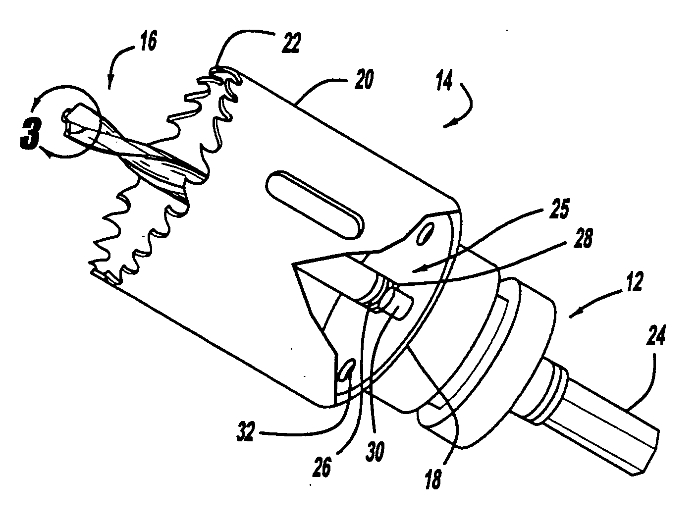
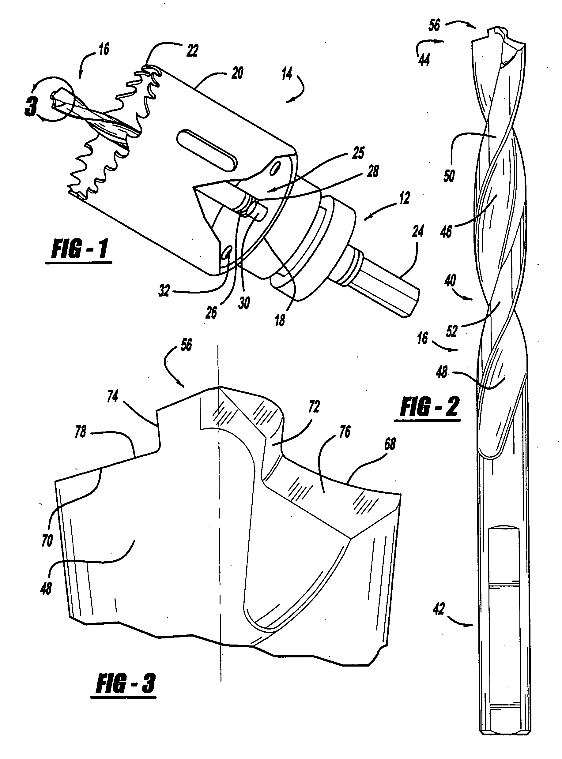
[0022] Turning to the figures, a hole saw is illustrated and designated with the reference numeral 10. The hole saw includes an arbor 12 coupled with a cup shaped cutting member 14. A drill bit 16 extends from the arbor 12 and cup shaped cutting member 14. The cup shaped cutting member 14 includes a base 18 with a unitary skirt 20. A plurality of teeth 22 are formed in the cup shaped cutting member at the end of the skirt 20.
[0023] The arbor 12 includes a shank 24 which secures into a drill or the like. The arbor 12 also includes a retaining portion 25 to retain the cup shaped cutting member 14 onto the arbor 12. The retaining portion 25 generally includes an extended threaded nipple 26 which is received into a threaded hole 28 in the base 18 of the cup shaped cutting member 14. This retains the cup shaped cutting member 14 onto the arbor 12. Also, the arbor 12 may include positioning members 30 which extend through apertures 32 in the base 18 to maintain the cup shaped cutting member 14 from rotating with respect to the arbor 12.
[0024] The cup shaped cutting member skirt 20 defines the diameter of the hole which is to be bored into the workpiece. The skirt 20 is an annular member of a desired diameter. Ordinarily, the diameter is greater than 9/16 of an inch.
[0025] The drill bit 16 includes a body portion 40, a shank 42 and a tip 44. The shank 42 is received in a bore of the arbor 14. The body portion 44 includes a pair of helical flutes 46 and 48 which terminate at the tip 44. The drill bit 16 includes a tapered web which improves the durability of the tip 44. The helical flutes 46, 48 are separated by a helical land 50, 52. The lands 50, 52 define the diameter of the twist drill body which remains constant along the body of the drill bit 16.
[0026] The tip 44 includes a pilot point 56 which extends from the terminus of the body portion 40 at a desired distance. The pilot point 56 includes a pair of inner minor cutting edges 58 and 60 and outer minor cutting edges 62 and 64. Also, a chisel point 66 may be formed between the inner cutting edges 58 and 60. In this embodiment, a split point pilot point is illustrated. A better description of the drill bit is provided in U.S. Ser. No. ______, filed on the same date as the present application, and entitled “Twist Drill With a Pilot Tip”, assigned to the same assignee, the specification and drawings of which are herein expressly incorporated by reference. However, a different type of cutting pilot point could be used.
[0027] The body terminus includes major cutting edges 68 and 70. The major cutting edges 68 and 70 radiate to define the outer diameter of the body portion 40. Also, the major cutting edges 68, 70 are substantially co-planar and pass through the longitudinal axis. The cutting edges 62 and 64 radiate to define the diameter of the pilot point 56. Thus, two different diameters are defined by the two pairs of cutting edges 68, 70 and 62, 64. Also, the first cutting edges 62, 64 are spaced forwardly from the major or second cutting edges 68 and 70.
[0028] The pilot point tip has curved sides 72 and 74. The curved sides 72 and 74 are angled inward from the minor outer cutting edges 62, 64 towards the major cutting edges 68, 70 at an angle a from 0.50 to 50 to provide clearance and relief for the cutting pilot point 56. The major cutting edges 68 and 70 include clearance surfaces 76 and 78. The clearance surfaces 76 and 78 are angled with respect to horizontal at an angle (CA) of about 8° to 12°. This provides clearance for the swarf as it is cut at the edges 68 and 70. The cutting edges 68 and 70, as well as the clearance faces 76 and 78, are angled from horizontal with respect to the longitudinal axis at an angle β from 0° to about 27° and preferably about 22° to about 27°. This angle β provides for efficient cutting of the drill bit at a speed of about 300 to about 1200 RPMs. It should be noted that this speed is significantly less than the speed of the drill bit by itself without the hole saw cup shaped cutting member 14. The speed of the drill bit by itself is about 1200 RPMs. Thus, the present drill bit provides efficient cutting at a much lower rpm.
[0029] The helical flute 46 and 48 terminate at the end of the body portion and at the pilot point 56. The flute surface defines the rake face of the cutting edges 68 and 70 as well as the rake face of cutting edges 62 and 64. The rake angle (RA) and clearance angle are defined to provide optimum cutting. The rake angle is between about 6° to about 10°. The rake angle is the same for both sets of cutting edges 62, 64 and 68, 70.
[0030] The pilot point diameter (d) is a percentage of the body portion diameter (D). The percentage is based upon the desired application of the drill bit. The diameter of the minor cutting edges is always smaller than the diameter of the major cutting edges. Also, the minor cutting edges create a first hole in the workpiece which prohibits the skipping or walking phenomenon. After the pilot point 56 has entered into the workpiece, the secondary cutting edges 68, 70 create a larger hole in the workpiece to further center the hole saw during operation. The second diameter is larger than that of the first. Thus, the drill bit efficiently centers the hole saw in position. Also, since the pilot point 56 rapidly enters the workpiece, followed by the entry of the secondary cutting edges 68, 70, this enhances the speed of which the hole saw cuts. It has been found that the pilot point tip minor cutting edges 62, 64 and the secondary cutting edges 68, 70 reduce the drilling time to drill a pilot hole by about 30%. This, in turn, reduces the overall drilling time of the hole saw by approximately 20%. Accordingly, the present invention drills a faster pilot hole, which, in turn, enables the hole saw to cut faster to drill a hole which is a desired feature.
[0031] The description of the invention is merely exemplary in nature and, thus, variations that do not depart from the gist of the invention are intended to be within the scope of the invention. Such variations are not to be regarded as a departure from the spirit and scope of the invention.

PUM

PropertyMeasurementUnit
Angle22.0°
Angle27.0°
Angle

Description & Claims & Application Information

We can also present the details of the Description, Claims and Application information to help users get a comprehensive understanding of the technical details of the patent, such as background art, summary of invention, brief description of drawings, description of embodiments, and other original content. On the other hand, users can also determine the specific scope of protection of the technology through the list of claims; as well as understand the changes in the life cycle of the technology with the presentation of the patent timeline. Login to view more.

Similar technology patents

Method for loading a pistol and a holster

Owner:TROSHKIN ALEKSANDR G +3

Panel with a slider

ActiveUS20180080488A1reduce timeimproved strength
Owner:VÄLINGE INNOVATION AB

Classification and recommendation of technical efficacy words

Why Eureka
Try Eureka