Golf ball performance evaluation system

Inactive Publication Date: 2007-05-10
BRIDGESTONE SPORTS
View PDF11 Cites 25 Cited by
  • Summary
  • Abstract
  • Description
  • Claims
  • Application Information

AI Technical Summary

Benefits of technology

[0011] According to the golf ball performance evaluation system of the invention, it becomes possible to evaluate the performance of the golf ball comprehensively and accurately by continuously measuring, with respect to the golf ball which is hit to fl

Problems solved by technology

Therefore, for example, assuming that a distance from the golf ball hitting position to the landing point is 210 m (about 230 yards), it has been difficult to estimate the shape of the trajectory and the behavior of t

Method used


Image

  • Golf ball performance evaluation system
  • Golf ball performance evaluation system
  • Golf ball performance evaluation system

Examples


Embodiment Construction

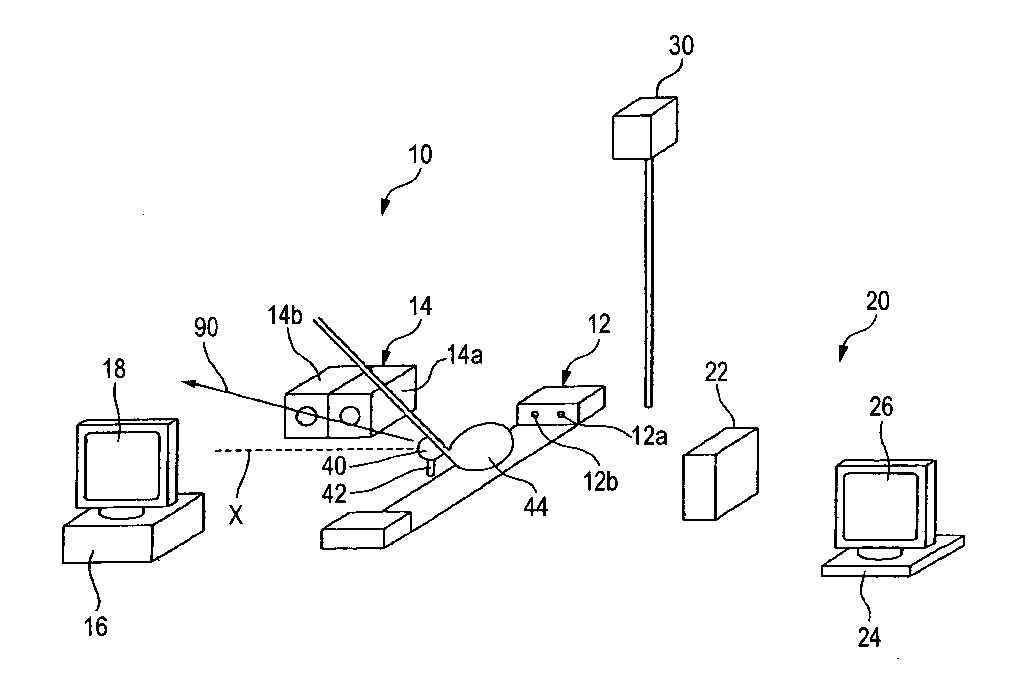
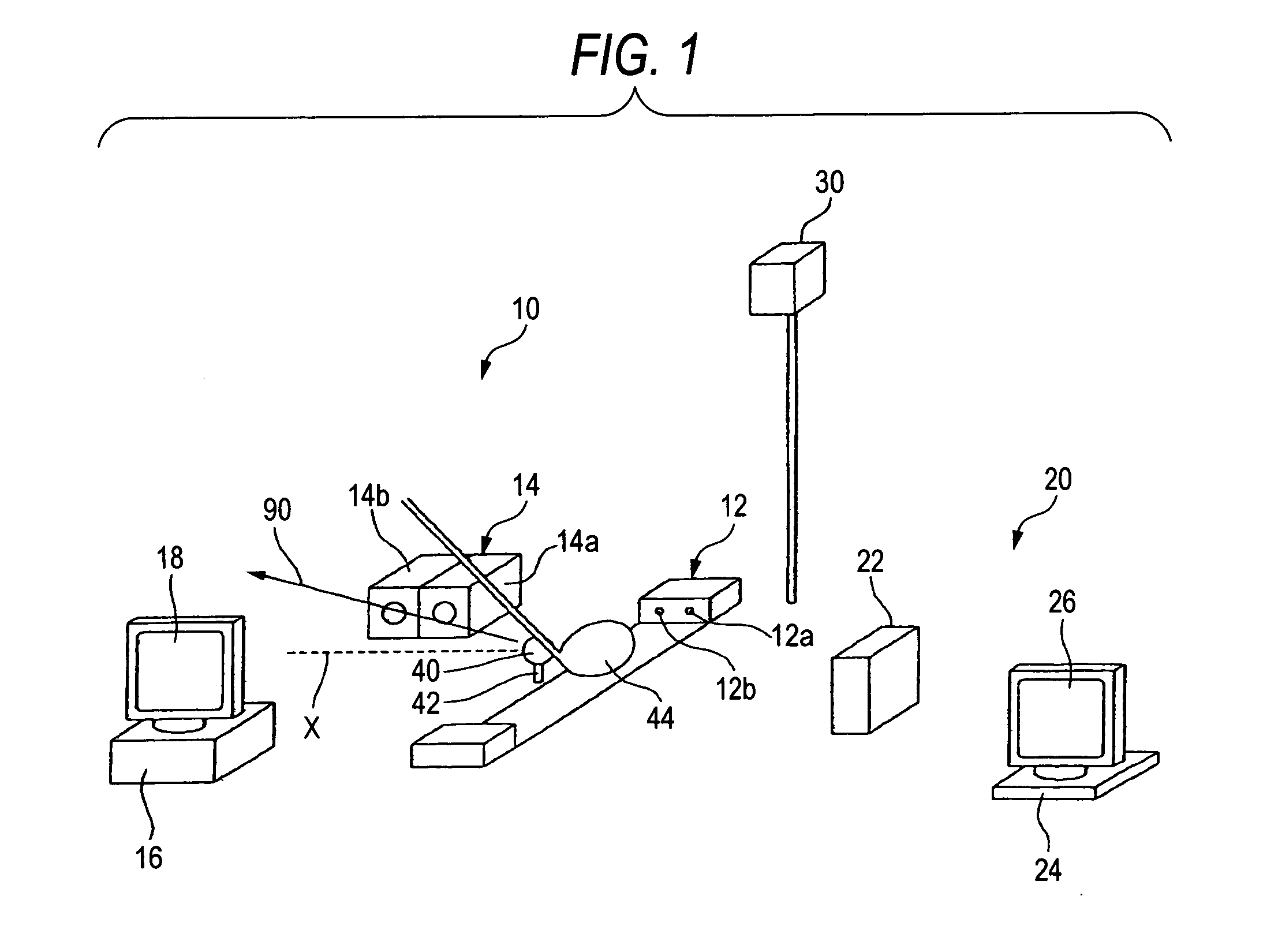
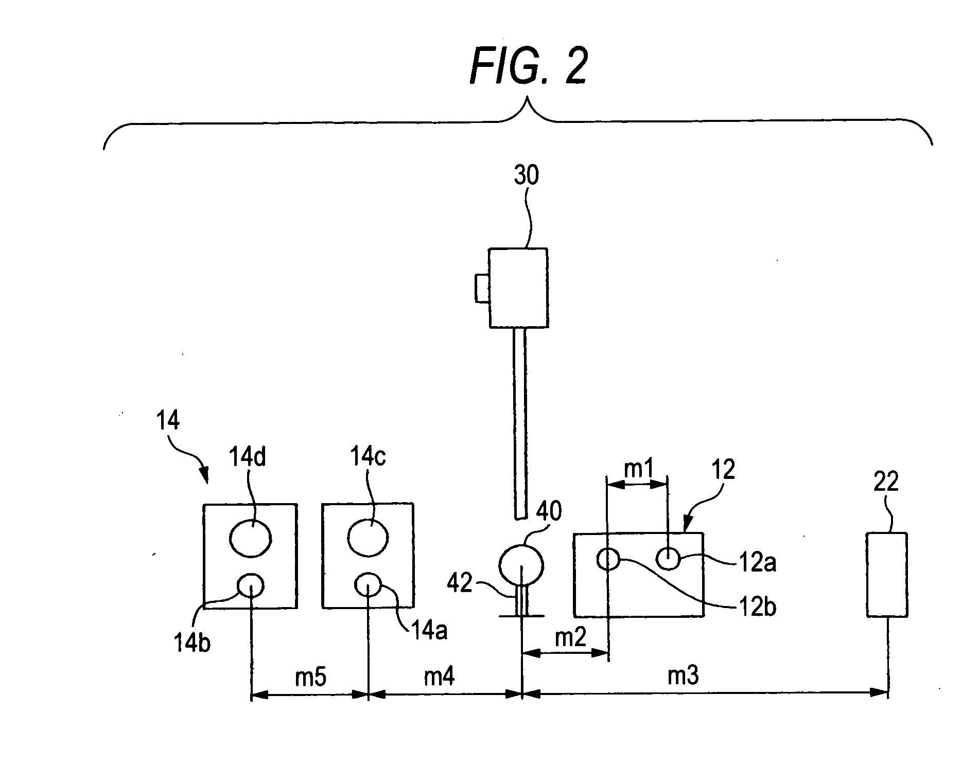
[0018] Hereinafter, an embodiment of the invention will be described with reference to the accompanying drawings, but the invention is not limited to the embodiment below. FIG. 1 is a schematic perspective view of a golf ball performance evaluation system according to an embodiment of the invention, and FIG. 2 is a schematic front view of the same system with a display unit thereof removed.

[0019] In FIGS. 1 and 2, reference numeral 10 denotes an initial properties analyzing unit. The initial properties analyzing unit 10 includes a sensor unit 12, a photographing unit 14 having two cameras placed to align with each other substantially horizontally in a direction in which a golf ball is hit to fly, and a properties analyzing unit 16 for analyzing and displaying photographed results. In addition, although not so illustrated, the sensor unit 12, the photographing unit 14 and the properties analyzing unit 16 are electrically connected. Additionally, in FIGS. 1 and 2, reference numeral 2...


PUM


Abstract

A golf ball performance evaluation system includes an initial properties analyzing unit for measuring and analyzing kinetic properties of a golf ball immediately after the golf ball is hit by a golf club, and an in-flight properties analyzing unit for measuring and analyzing kinetic properties of the golf ball hit by the golf club during a flight on its trajectory.

Description

BACKGROUND OF THE INVENTION [0001] 1. Field of the Invention [0002] The present invention relates to a golf ball performance evaluation system and more particularly to a golf ball performance evaluation system for measuring and analyzing not only kinetic properties of a golf ball immediately after the golf ball is hit by a golf club but also kinetic properties of the golf ball which continues to fly on its trajectory (flying path) to draw a parabola. [0003] 2. Description of the Related Art [0004] conventionally, flying properties (flight properties) of a golf ball are measured and analyzed by actually hitting the golf ball with a golf club to obtain some properties of the golf ball such as speed (initial velocity), angle (hitting angle), spin amount and the like which result immediately after the golf ball is hit, and when required, a trajectory and distance of the golf ball so hit are calculated through simulation using the properties of the golf ball obtained as described above (...

Claims


Application Information

Patent Timeline
IPC IPC(8): A63B69/36
CPCA63B24/0003A63B24/0021A63B43/008A63B69/3614A63B69/3658A63B71/06A63B2024/0031A63B2024/0034A63B2207/02A63B2220/05A63B2220/16A63B2220/30A63B2220/35A63B2220/805A63B2220/807A63B2220/89G01S13/58G01S13/88A63B2225/74
Inventor SHIMIZU, TAKUICHI
Owner BRIDGESTONE SPORTS
Why Eureka
Try Eureka