Needle shield assembly having hinged needle shield and flexible cannula lock

a technology of hinged needle shield and flexible cannula lock, which is applied in the field of needle shield assemblies, can solve the problems that accidental needle sticks from used hypodermic needles can transmit diseases, and achieve the effect of deflecting the end portion

Inactive Publication Date: 2007-05-10
BECTON DICKINSON & CO
View PDF99 Cites 28 Cited by
  • Summary
  • Abstract
  • Description
  • Claims
  • Application Information

AI Technical Summary

Benefits of technology

[0008] A needle shield assembly of the present invention includes a needle cannula having a proximal end, a distal end and a lumen therethrough. A hub is provided having a proximal end for connecting to a medical device such as a syringe and a distal end connected to the proximal end of the needle cannula. A base member is connected to or integral with the hub. A needle shield is coupled to the base member by a hinge. A locking assembly having one or more locking members for engaging the needle cannula is provided. The locking member includes an end portion and a base portion. The end portion is relatively flexible while the base portion is relatively stiff. The shaft of a needle cannula can accordingly deflect the end portion of the locking member relatively easily upon entering the needle shield cavity. If the needle shield is pivoted in an attempt to re-expose the trapped needle cannula, the shaft of the needle cannula will engage the more rigid base portion of the locking member.

Problems solved by technology

Accidental needle sticks from used hypodermic needles can transmit disease.

Method used


Image

  • Needle shield assembly having hinged needle shield and flexible cannula lock
  • Needle shield assembly having hinged needle shield and flexible cannula lock
  • Needle shield assembly having hinged needle shield and flexible cannula lock

Examples


Embodiment Construction

[0025] While this invention is satisfied by embodiments in many different forms, there is shown in the drawings and herein described in detail, a preferred embodiment of the invention with the understanding that the present disclosure is to be considered exemplary of the principles of the invention and is not intended to limit the invention to the embodiment illustrated. The scope of the invention is measured by the appended claims and their equivalents.

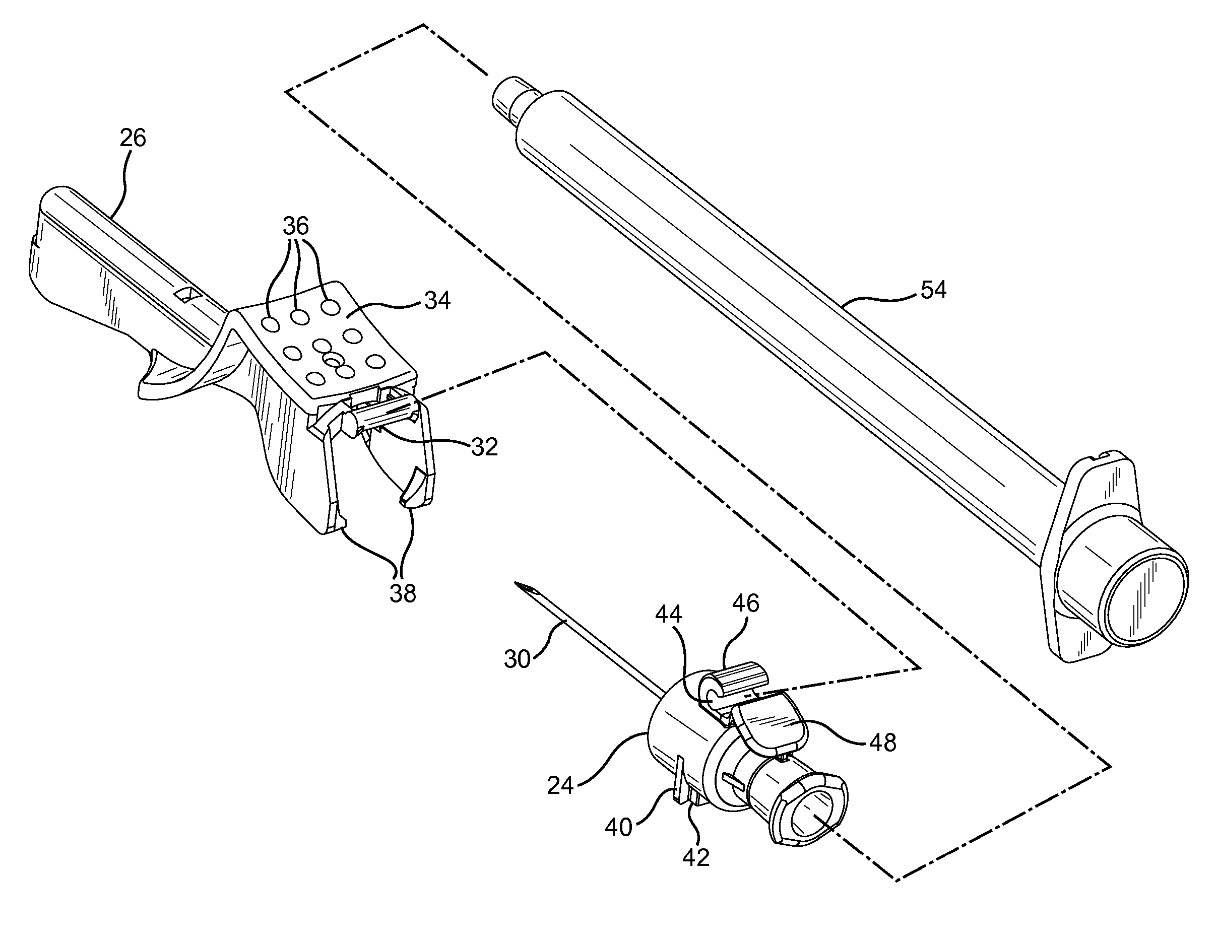
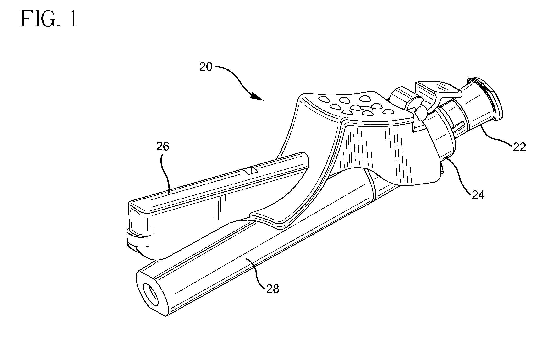
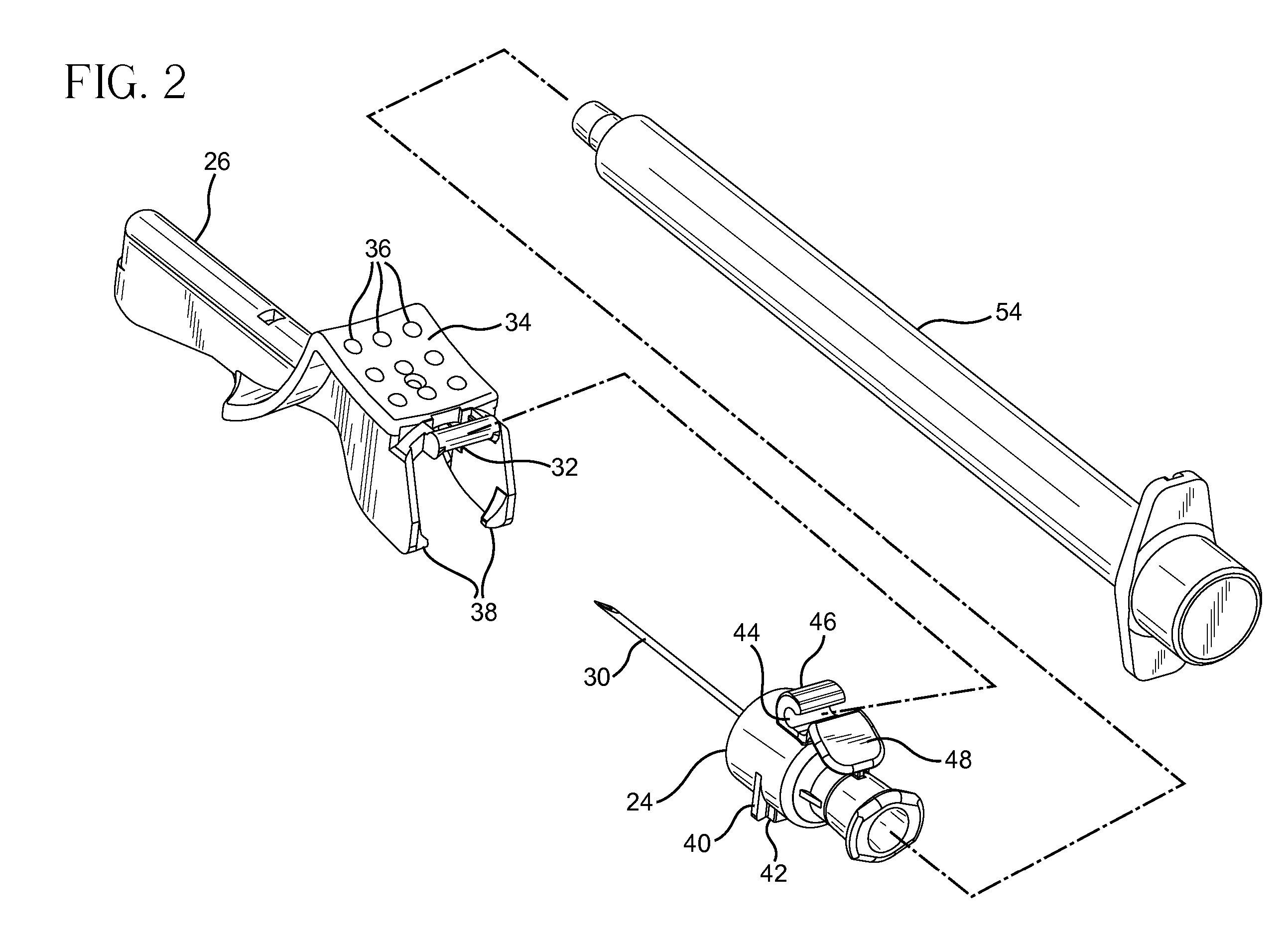
[0026] Referring to FIGS. 1 and 2, a needle shield assembly 20 is provided that includes a needle hub 22, a base member 24 connected to or integral with the needle hub, a needle shield 26, and a needle cover 28. The needle shield includes a proximal end portion that can be connected to the needle hub or base member, and a distal end portion that includes an elongate cavity for enveloping at least part of a needle cannula 30. The proximal end portion of the needle shield 26 includes an integral hinge pin 32 and a curved upper surface...


PUM


Abstract

A needle shield and needle shield assembly are provided for preventing accidental needle sticks. The needle shield includes opposing sidewalls and is pivotable between an open position that allows use of the needle cannula and a closed position that covers at least the tip of the needle cannula. A locking member extends from one of the sidewalls of the needle shield and includes a relatively rigid base portion and a relatively flexible end portion. The needle cannula engages the relatively flexible end portion when entering the needle shield cavity, deflecting it with respect to the base portion. Upon any attempt to move the needle shield from the closed position to the open position, the needle cannula is directed by the locking member towards the relatively rigid base portion, thereby making it very difficult to reuse the needle cannula.

Description

[0001] This application is a continuation of U.S. application Ser. No. 10 / 488,881, which was filed on Mar. 4, 2004, which claims the benefit of International (PCT) Application No. PCT / US02 / 20333, filed Jun. 27, 2002, which claims benefit of U.S. Provisional Application No. 60 / 303,940 filed Jul. 9, 2001.FIELD OF THE INVENTION [0002] The field of the invention relates to needle shield assemblies for medical devices such as hypodermic needles. BACKGROUND OF THE INVENTION [0003] Accidental needle sticks from used hypodermic needles can transmit disease. Accordingly, various types of needle shields have been designed to reduce the possibility of accidental sticks. [0004] A needle shield that is hinged near the base of the needle has the advantage of allowing one handed needle reshielding. A number of prior art needle shield assemblies including such needle shields have been developed. [0005] Various means have been provided for locking a hinged needle shield in the closed (needle protect...

Claims


Application Information

Patent Timeline
Patent Type & Authority Applications(United States)
IPC IPC(8): A61M5/32A61M5/00A61G12/00
CPCA61M5/3216
Inventor HWANG, CHARLES
Owner BECTON DICKINSON & CO
Why Eureka
Try Eureka