Vehicle driving assist system

a technology for assist systems and vehicles, applied in scene recognition, instruments, tractors, etc., can solve the problems of large risk potential and inability to provide visual information to drivers

Inactive Publication Date: 2007-05-10
NISSAN MOTOR CO LTD
View PDF5 Cites 127 Cited by
  • Summary
  • Abstract
  • Description
  • Claims
  • Application Information

AI Technical Summary

Benefits of technology

[0006] A vehicle driving assist system provides information via the sense of touch by controlling an actuation reaction force of a driver-operated device in accordance with a risk potential calculated based on conditions related to obstacles existing in the vicinity of the host vehicle (hereinafter called the “obstacle situation”). However, a vehicle driving assist system that conveys information via the sense of touch alone does not provide the driver with visual information indicating which obstacle is being targeted by the control and how large the risk potential is for that obstacle. Therefore, there exist a need for a system that executes actuation reaction force control based on the risk potential and also conveys visual information to make the state of the actuation reaction force control more readily understandable to the driver.

Problems solved by technology

However, a vehicle driving assist system that conveys information via the sense of touch alone does not provide the driver with visual information indicating which obstacle is being targeted by the control and how large the risk potential is for that obstacle.

Method used


Image

  • Vehicle driving assist system
  • Vehicle driving assist system
  • Vehicle driving assist system

Examples


first embodiment

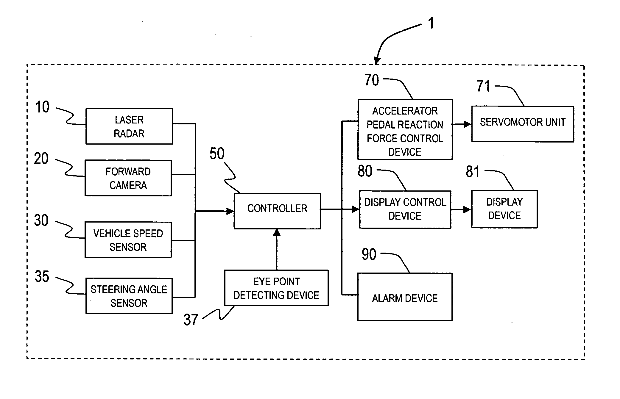
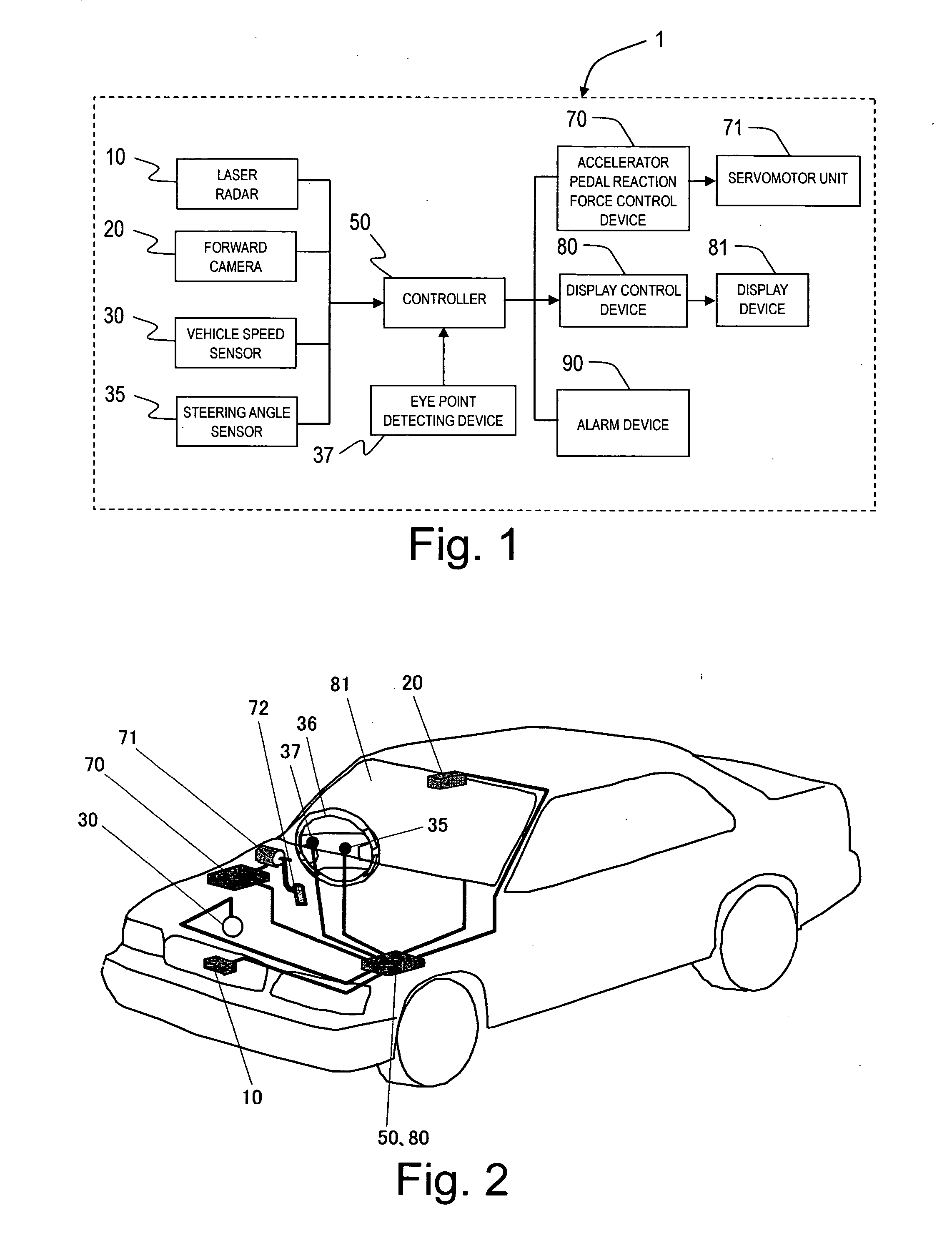
[0050] Referring initially to FIGS. 1 and 2, a vehicle driving assist system 1 is illustrated that is installed on a host vehicle (FIG. 2) in accordance with a first embodiment of the present invention. In particular, FIG. 1 is a system diagram showing the constituent features of a vehicle driving assist system 1 in accordance with a first embodiment of the present invention, while FIG. 2 is a diagrammatic view of a vehicle having the host vehicle driving assist system installed therein. The main features of the vehicle driving assist system 1 will now be explained. The vehicle driving assist system 1 is equipped with a laser radar 10, a forward camera 20, a vehicle speed sensor 30, a steering angle sensor 35 for detecting a steering angle of a steering wheel 36, an eye point detecting device 37, a controller 50, a driving force control device 60, an accelerator pedal reaction force control device 70, a servomotor unit 71 built into a linkage mechanism of an accelerator pedal 72, a ...

second embodiment

Variation on Second Embodiment

[0119] In this variation, instead of displaying the image captured by the forward camera 20, an image of the obstacle targeted by the calculation of the risk potential RP is generated based on the detection results of the laser radar 10 and the forward camera 20 and the generated image is displayed on the display monitor 81. The system 1 is further configured such that plurality of images are generated showing the obstacle from different directions and the driver can select which of the images is displayed.

[0120] Diagrams (a) to (c) of FIG. 17 illustrate examples of generated images. A risk potential marker 82 indicating the target of the calculation of the risk potential RP is displayed in an overlapping manner over the image 84 of a preceding vehicle. The size, color, and shape of the risk potential marker 82 are determined in the same manner as described regarding the first embodiment. Diagram (a) of FIG. 17 is an example of a generated image showin...

third embodiment

[0125] A vehicle driving assist system in accordance with a third embodiment of the present invention will now be explained. The basic constituent features of a vehicle driving assist system in accordance with the third embodiment are the same as those of the first embodiment shown in FIGS. 1 and 2. The third embodiment will be explained chiefly by describing its differences with respect to the first embodiment.

[0126] In the third embodiment, the display position of the risk potential marker 82 displayed on the display device 81 is changed in accordance with the degree of convergence between the host vehicle and the preceding vehicle. More specifically, when the host vehicle draws closer to the preceding vehicle, position of the risk potential marker 82 is lowered so as to approach the vehicle in a virtual (imaginary) manner. Meanwhile, when the host vehicle draws farther away from the preceding vehicle, the position of the risk potential marker 82 is raised so as to move away from...


PUM


Abstract

A vehicle driving assist system is configured to convey a risk potential relating to a preceding obstacle to a driver using both visual information and haptic information. For example, the vehicle driving assist system executes accelerator pedal actuation reaction force control such that an actuation reaction force is generated in accordance with a risk potential that expresses a degree of convergence between the host vehicle and a preceding obstacle. In order to convey to the driver in a clear manner which preceding obstacle(s) is an obstacle targeted by the risk potential calculation and the reaction force control, the system displays a reference frame or marker at a position corresponding to the targeted obstacle (preceding vehicle). At least one of size, color, shape and brightness of the marker is set in accordance with the risk potential.

Description

CROSS-REFERENCE TO RELATED APPLICATIONS [0001] This application claims priority to Japanese Patent Application Nos. 2005-325065, filed on Nov. 9, 2005, and 2006-233141, filed on Aug. 30, 2006. The entire disclosures of Japanese Patent Application Nos. 2005-325065 and 2006-233141 are hereby incorporated herein by reference. BACKGROUND OF THE INVENTION [0002] 1. Field of the Invention [0003] The present invention relates to a vehicle driving assist system configured to assist a driver with respect to the operation of a host vehicle. More specifically, the present invention relates to a vehicle driving assist system that visually conveys information to the driver about a preceding obstacle that is determined to be a potential risk to the host vehicle. [0004] 2. Background Information [0005] Several conventional vehicle driving assist systems have been proposed for conveying information to a driver of a host about a preceding obstacle that is determined to be a potential risk to the hos...

Claims


Application Information

Patent Timeline
Patent Type & Authority Applications(United States)
IPC IPC(8): G08G1/16B60K26/04B60K28/00B60K35/00B60R1/00B60R21/00B60T7/12B60W30/16B60W50/14B60W50/16
CPCB60K26/021B60K35/00B60K2350/1084B60K2350/2008B60W30/08B60W40/02B60W50/16B60W2540/22B60R1/00G02B27/01B60R2300/205B60R2300/301B60R2300/308B60R2300/8033B60R2300/8093G02B2027/0141G02B2027/014B60K2370/152B60K2370/179B60K2370/188B60K2370/21B60K2370/334B60K2370/52B60K2370/1529B60W2540/221G06V20/58B60R21/0134B60W2050/146B60W2552/50
Inventor KONDOH, TAKAYUKI
Owner NISSAN MOTOR CO LTD
Why Eureka
Try Eureka