[0005] The object on which the invention is based is to specify an operating table of the type mentioned in the introduction, which allows greater
latitude in the adjustment of the bed about its axis of inclination and / or axis of tilt and in the vertical direction.
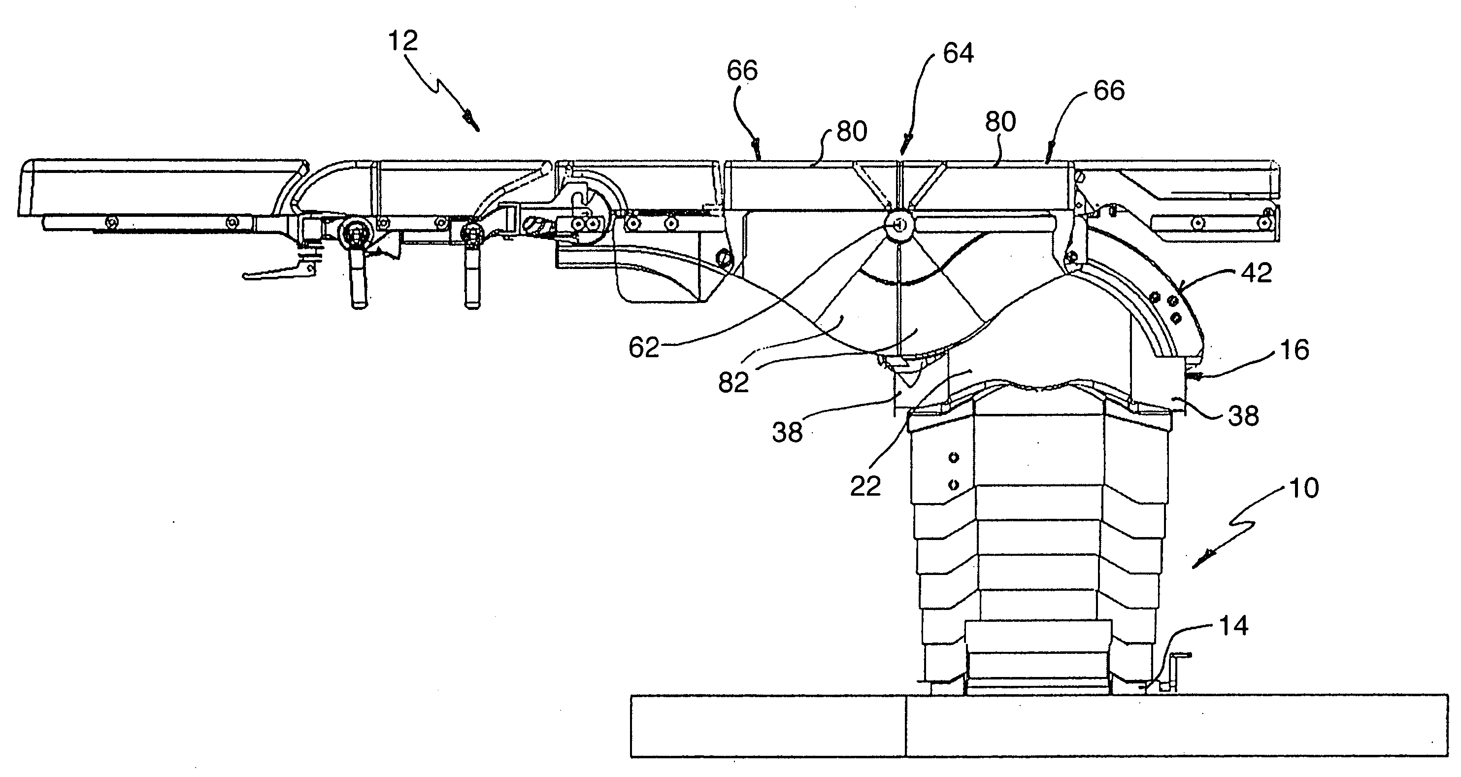
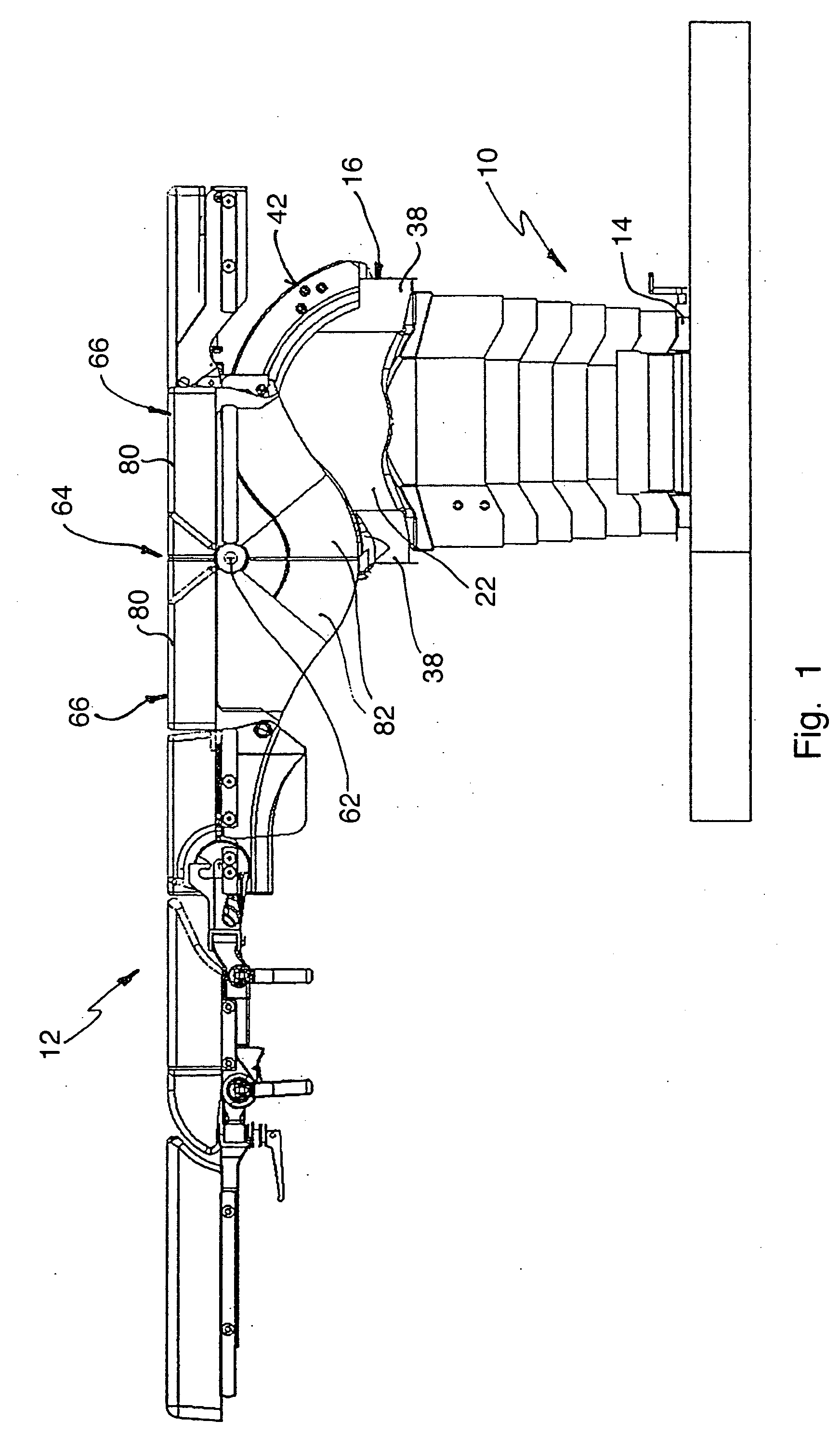
[0007] Since the
saddle coupled to the patient bed slides externally on the curved guide track, there is no need for the pivot axis to be mounted so as to pass through the column head. This gives rise, within the column head, to
free space which is available for height adjustment and allows a greater lift of the height drive. In particular, this type of construction also makes it possible for the column head together with the patient bed to be lowered to a greater extent. Since, at least in the case of a convexly curved guide track, the saddle can be moved as far as the end of the respective guide track, the
angle of inclination of the patient bed can also be made very large correspondingly to the curvature of the guide track, without the patient bed butting against the column head.
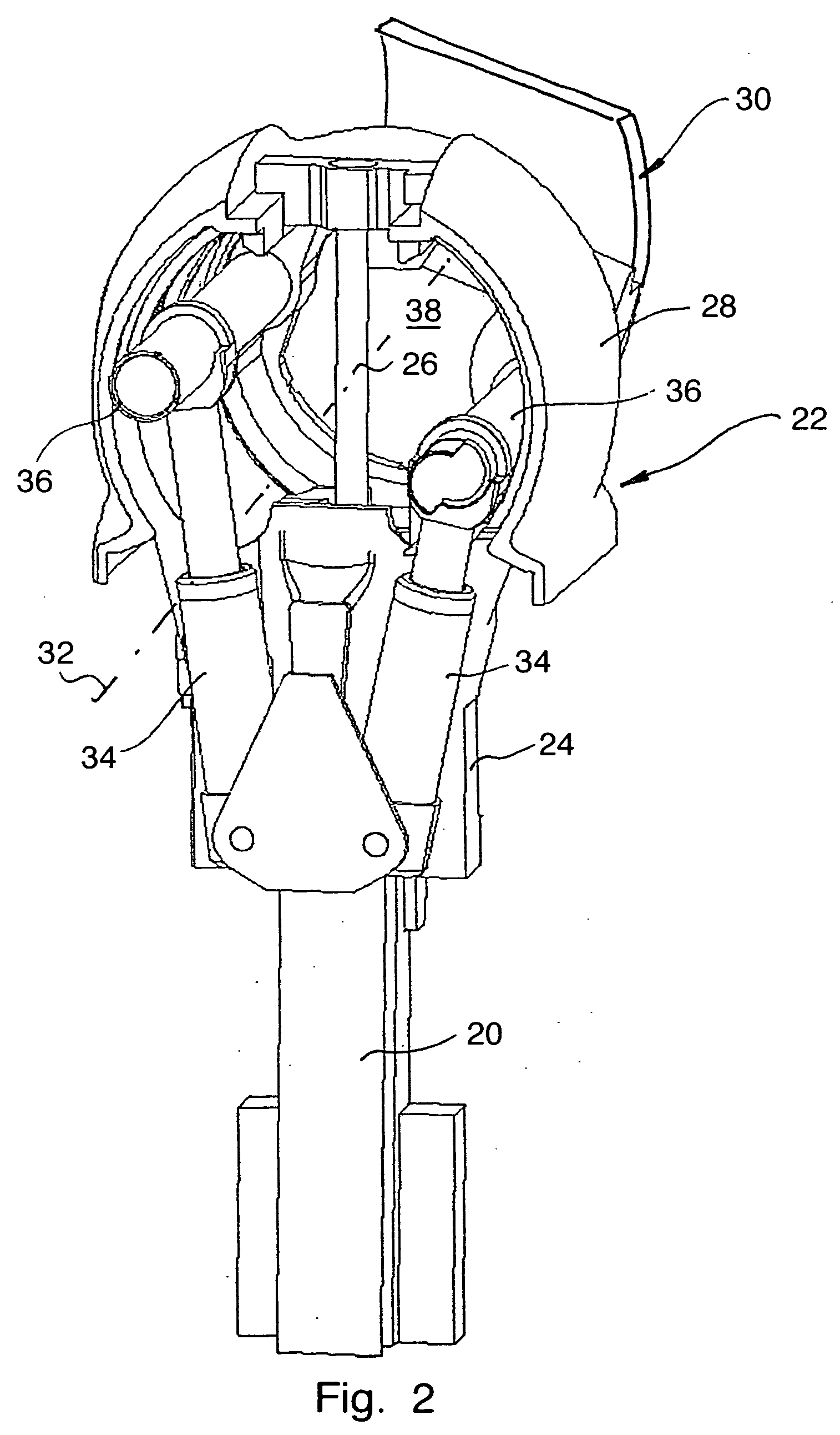
[0009] Preferably, the saddle drive has at least one push and / or pull element which is flexible at least in one direction and which is guided displaceably along the guide track and is connected, on the one hand, to the saddle and, on the other hand, to an
actuator. A saddle drive can thereby be provided which, on the one hand, can exert a high force and, on the other hand, occupies only a small amount of space. Preferably, the
actuator is a
linear drive, for example a pressure-medium-actuated cylinder. A particularly space-saving and yet functionally reliable design of the saddle drive can be achieved in that the push and / or pull element is a rigid-back chain which can bend in only one direction. Such a chain can be connected directly to the
piston of the pressure-medium-actuated cylinder and forms as it were a rigid
piston rod which is nevertheless bendable, that is to say deflectable, on one side. A
linear drive can thereby be provided, the
stroke of which corresponds approximately to its overall length and in which no additional space is required for the extension of the
piston rod.
[0012] To pivot the head frame about its pivot axis, it is proposed that the pivoting drive comprise two pressure-medium-actuated pivoting cylinders which are arranged within the column and, on the one hand, are supported on the column head and, on the other hand, engage on the head frame on both sides of the pivot axis. In this way, the necessary force for pivoting the patient bed can be applied conveniently. In another possibility, the pivoting drive comprises at least one worm wheel connected fixed in terms of rotation to the head frame and arranged coaxially with respect to the pivot axis and a worm which can be driven by means of a motor and is in engagement with the worm wheel.
[0015] In the preferred embodiment in which the axis of curvature of the guide track is identical to the axis of inclination, the pivoting of the patient bed about its pivot axis affords a further
advantage, in combination with the displacement of the saddle on the guide track. When the saddle is displaced from one end of the guide track towards to the other end of the guide track, the patient bed can always be kept in a horizontal position by the latter simultaneously being pivoted in the opposite direction. The final effect is a horizontal displacement of the patient bed with respect to the supporting column, without a specific guide or a specific drive being required for this purpose. Moreover, in this case, in the position of the saddle at the end of the guide track, an additional lowering of the patient bed with respect to the middle position of the saddle, that is to say the highest point of the guide track, also occurs, without a height adjustment of the column head being required for this purpose. When the saddle is displaced towards one end and the patient bed pivots in the same direction, the pivot angles are added up to form a very large achievable
angle of inclination.

