System and method for laser detector with marker

a laser detector and marker technology, applied in the field of light detection devices, can solve the problems of difficult reading of laser projected by only providing a projected image of the laser emitting device,

Inactive Publication Date: 2007-05-17
BLACK & DECKER INC
View PDF18 Cites 20 Cited by
  • Summary
  • Abstract
  • Description
  • Claims
  • Application Information

AI Technical Summary

Benefits of technology

[0004] Typically, however, laser emitting devices only provide a projected image, which can be obscured if the light source is obstructed. In addition, the laser projected by the laser emitting devices can be difficult for the user to read in certain lighting conditions. Accordingly, it would be desirable to provide a device, such as a light detector, that is capable of identifying the laser projected by the laser emitting device and that further includes a marking system that can indicate the exact position of the laser on the work-piece in a manner that is easily viewable by a user.

Problems solved by technology

Typically, however, laser emitting devices only provide a projected image, which can be obscured if the light source is obstructed.
In addition, the laser projected by the laser emitting devices can be difficult for the user to read in certain lighting conditions.

Method used


Image

  • System and method for laser detector with marker
  • System and method for laser detector with marker
  • System and method for laser detector with marker

Examples


Embodiment Construction

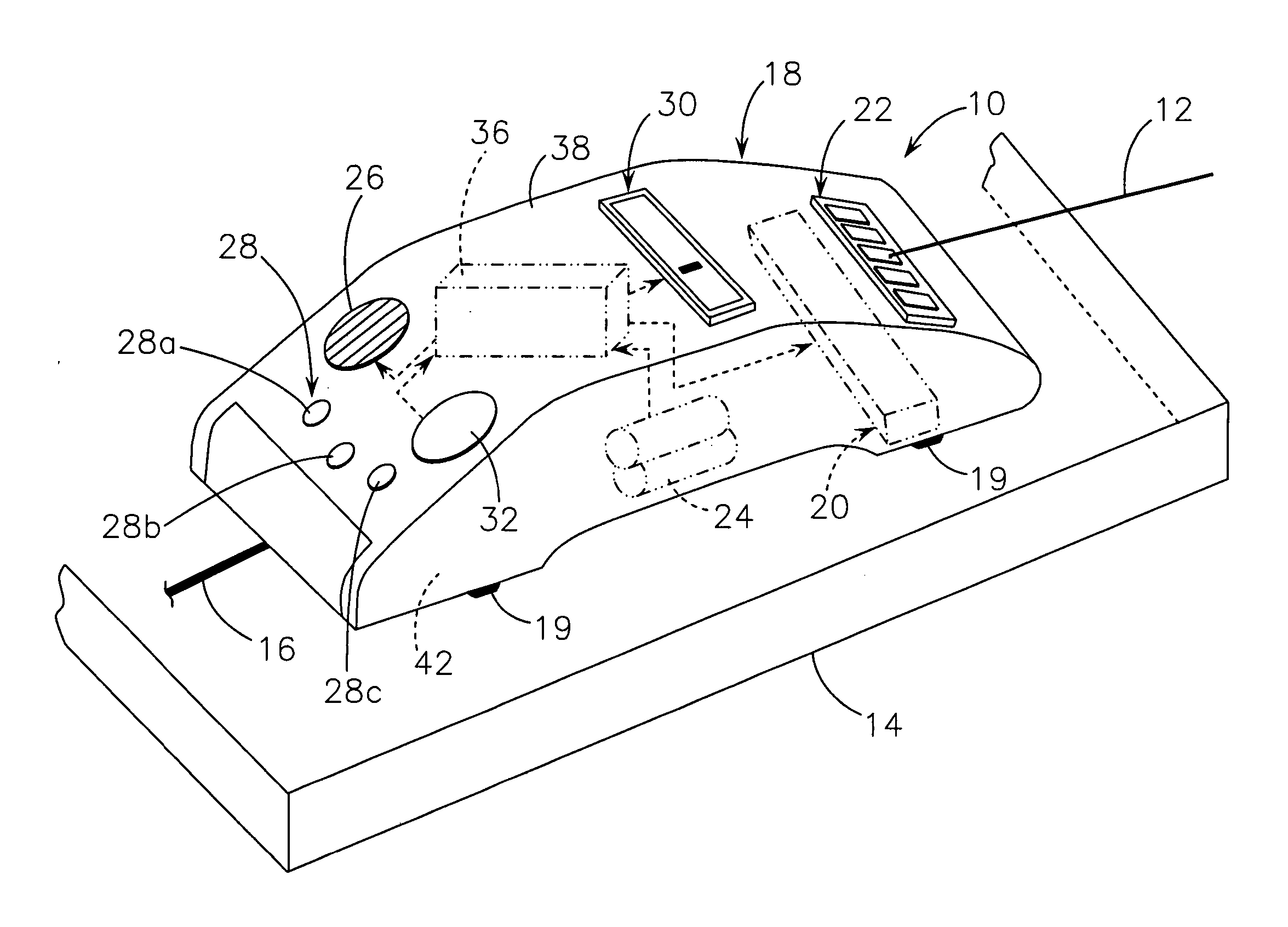
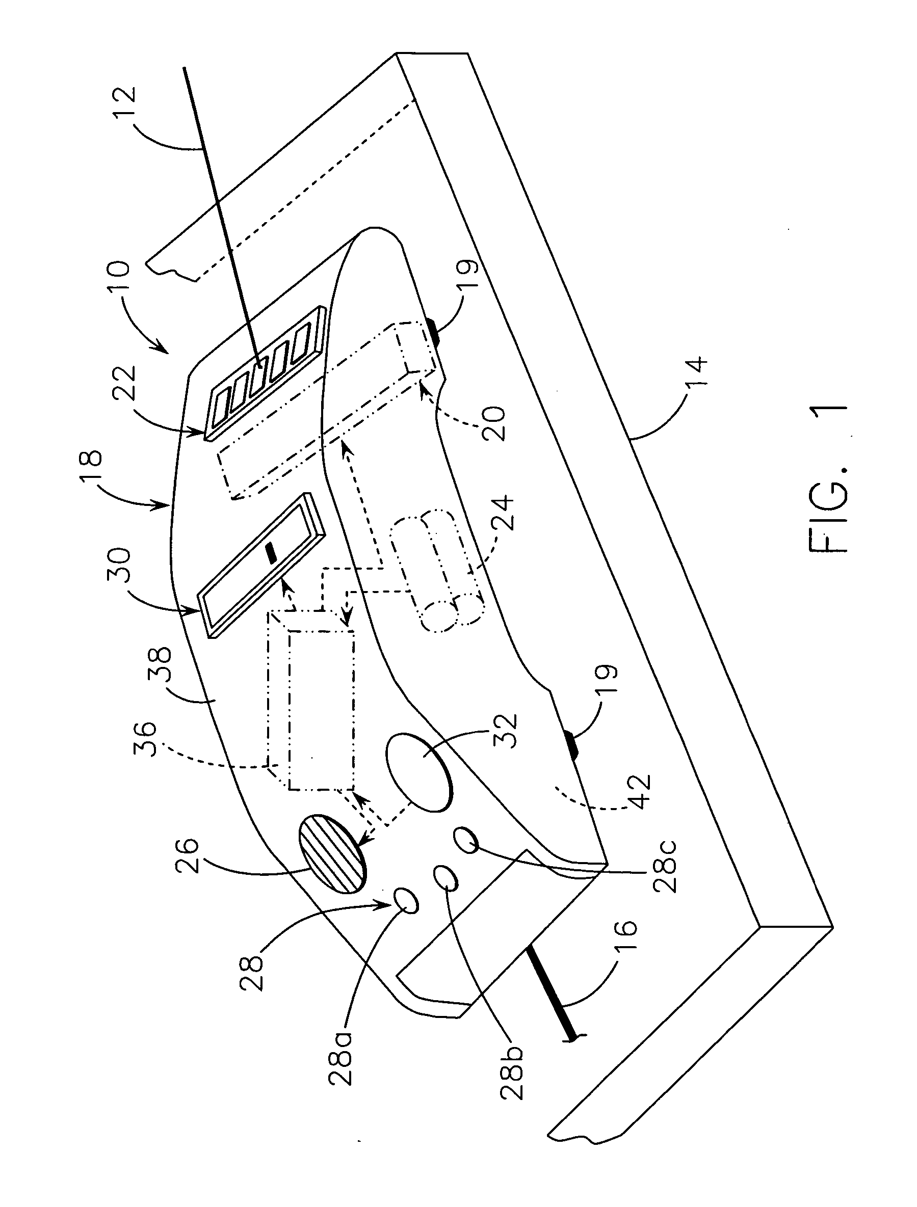
[0019] The following description of various embodiments is merely exemplary in nature and is in no way intended to limit the present teachings. Although the following description is related generally to a light detector including a marker to mark the position of a projected laser beam onto a work surface or work-piece, it will be understood that the light detector and / or the marker, as described and claimed herein, can be used in combination with any appropriate tool, such as a level or stud finder. Therefore, it will be understood that the following discussions are not intended to limit the scope of the appended claims.

[0020] With reference to FIG. 1, an exemplary light detector system or light detector 10 is shown. The light detector 10 can be used to detect a location of a projected planar light source, such as a laser beam 12, and can enable an operator to indicate or mark the location of the projected laser beam 12 on a surface of a work-piece or work-piece 14 via a marking 16...


PUM


Abstract

A light detector system for use with a work-piece is provided. The light detector system can include a housing and at least one sensor coupled to the housing. The sensor can be responsive to a light source to generate a signal that indicates a location of the light source with respect to the housing. The light detector system can also comprise a marker coupled to the housing. The marker can be responsive to the signal to mark the location of the light source on a surface of the work-piece.

Description

CROSS-REFERENCE TO RELATED APPLICATIONS [0001] The present application claims the benefit of U.S. Provisional Application No. 60 / 735,133, filed on Nov. 9, 2005.INTRODUCTION [0002] The present invention relates generally to a light detection device, and more particularly to a system and method for a light detector including a marker for marking the location of the detected light on a work-piece. [0003] Traditionally, lasers have been employed in the construction industry to assist in the preparation of surfaces for cutting operations and in the alignment of objects. For example, a laser emitting device can be used to generate a horizontal or vertical line that can comprise a cutting path for machining a work-piece to assist the user in producing an accurate cut. Further, lasers can be used with levels to project a horizontal or vertical line to enable a user to ensure that multiple objects are properly aligned. [0004] Typically, however, laser emitting devices only provide a projecte...

Claims


Application Information

Patent Timeline
Patent Type & Authority Applications(United States)
IPC IPC(8): G01C5/00
CPCG01C15/006
Inventor SERGYEYENKO, MARGARITA
Owner BLACK & DECKER INC
Why Eureka
Try Eureka