
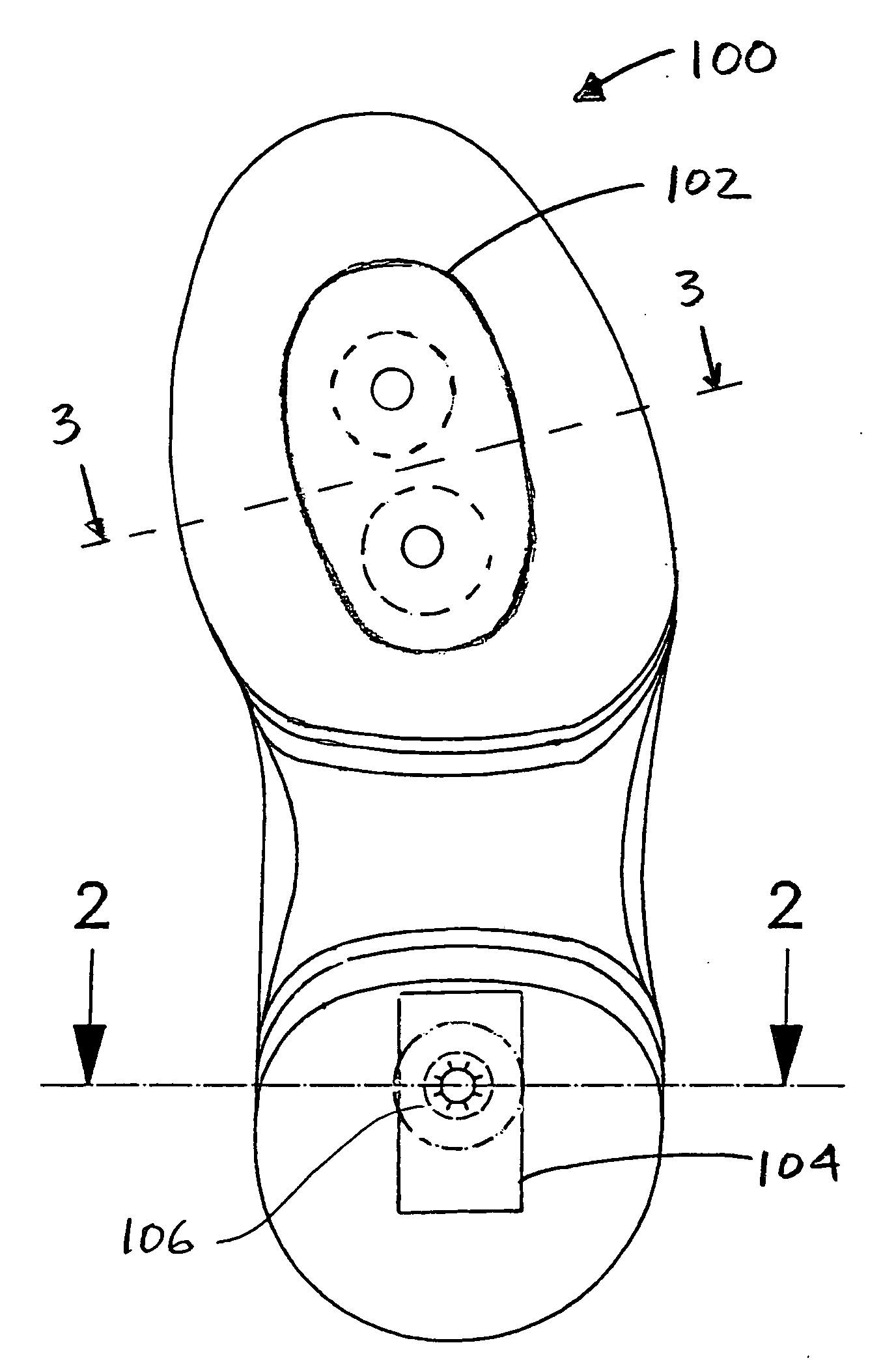
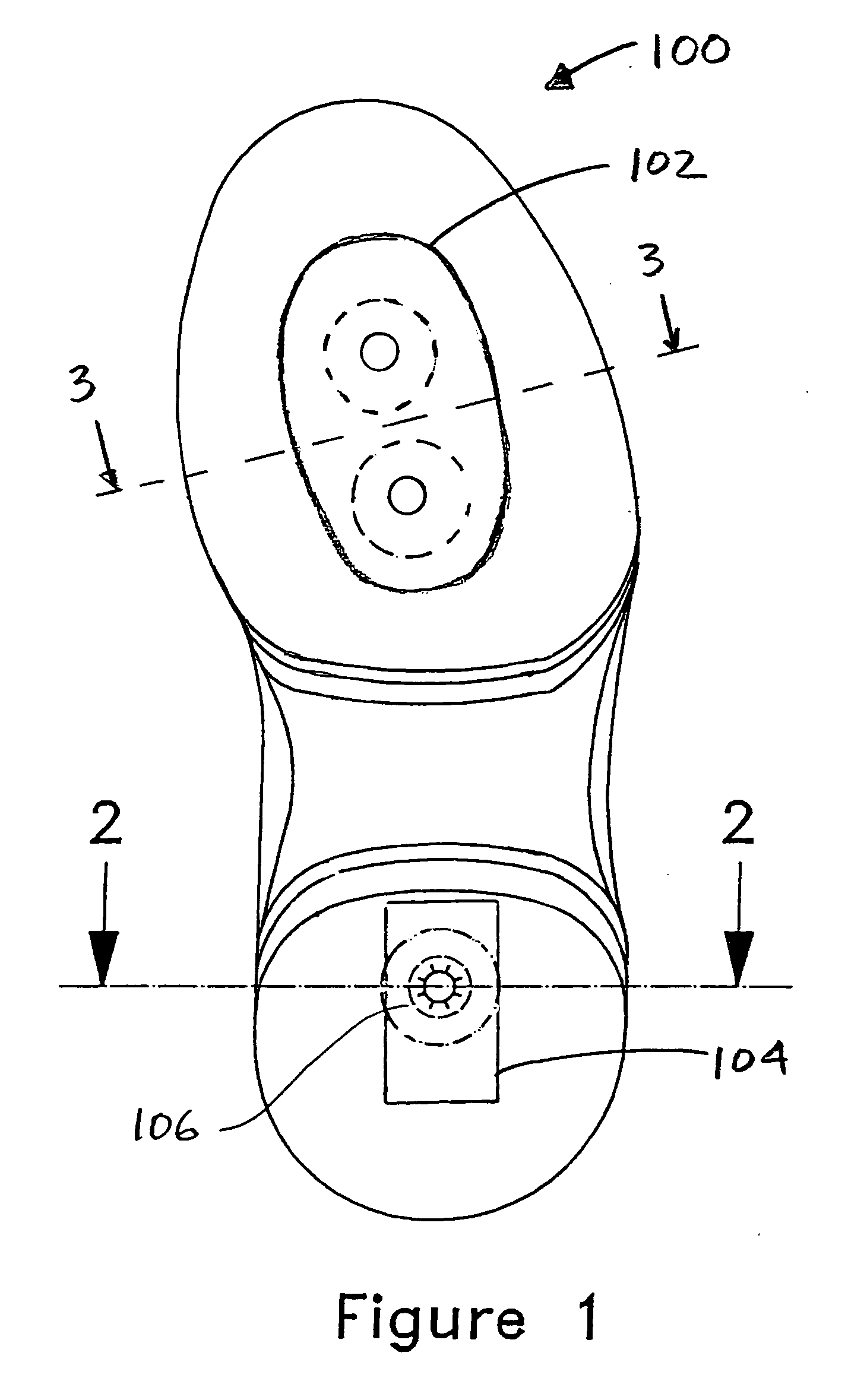
Variable surface sole for bowling and other shoes

a bowling and other shoe technology, applied in the field of performance shoes, can solve the problems of a step change and no continuous adjustability, and achieve the effect of raising or lowering

Inactive Publication Date: 2007-05-17
ETONIC WORLDWIDE
View PDF16 Cites 12 Cited by
  • Summary
  • Abstract
  • Description
  • Claims
  • Application Information

AI Technical Summary

Benefits of technology

[0011] The ability to adjust the heel or foresole, front-to-back and side-to-side can also provide benefits in other performance characteristics that do not depend significantly on the user's sensitivity to sliding friction, but do depend on comfort or safety. In this respect, the present invention can provide pronation adjustment at the exterior of the sole, whether or not sliding and / or braking are important performance considerations.
[0012] Another advantage achievable with the present invention, is the ability to effectuate a reverse inclination on either the heel or foresole. Bowling, athletic, and other performance shoes, as well as street shoes, are universally manufactured with the main weight bearing, ground contacting surfaces of the heel in substantially the same plane as the main weight bearing, ground contacting surfaces of the foresole. In other words, the foresole and heel lie flat on a flat surface. As an example with an adjustable heel according to the invention, the neutral adjustment position can correspond to the conventional coplanar relationship between the heel and the foresole, but with adjustment options the back region of the heel weight bearing surface can be effectively raised or lowered. This added capability can be attractive to some bowlers who have unusual approaches, foot shapes, or braking tendencies.
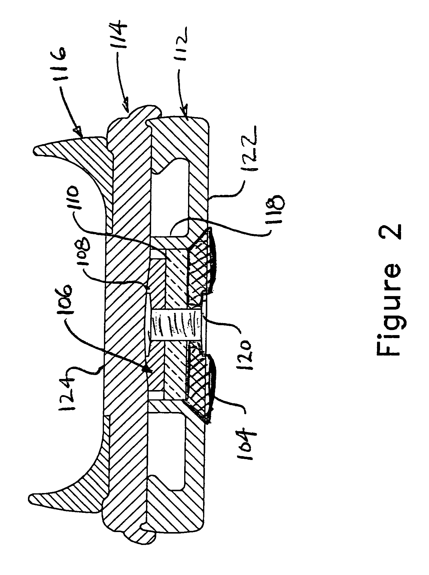
[0015] The adjustment device can take a variety of forms. In one embodiment, one disc is embedded in a base portion of the sole, such as in the midsole, and another disc is embedded in a movable pad of the sole, with a threaded bore for receiving a worm screw or the like that has its drive end accessible at the exterior of the sole. With a screw driving device such as an Allen wrench or the like, the user can readily displace the disc in the movable pad relative to the stationary disc in the base of the sole, thereby raising or lowering the pad. This can be implemented for continuous adjustment, or be ratcheted for repeatable stepwise adjustment.

Problems solved by technology

Although this technique has enjoyed some commercial success, it has the disadvantages of requiring a bowler to carry a kit of varying replacement pads and, even with such a variety of pads, each adjustment increment is a step change, without continuous adjustability.

Method used


Image

  • Variable surface sole for bowling and other shoes
  • Variable surface sole for bowling and other shoes
  • Variable surface sole for bowling and other shoes

Examples


embodiment 200

[0033]FIG. 4 illustrates another embodiment 200 where the pads 202, 204 are situated on either lateral side of the centerline, in the foresole. Each of these pads can be the same as, or variations of the pads and actuator shown in FIGS. 2 and 3. One or two pads can optionally be situated in the center or forward regions of the foresole.

embodiment 300

[0034]FIG. 5 illustrates another embodiment 300 where larger pad or platform 302 supports a plurality of cleats 304 that extend outwardly, for example, in a hiking or similar boot. In this instance, the adjusting device 306 adjusts the platform 302 into and out of the shoe, whereas the cleats 304 provide the texture, thus effective friction, for the foresole and / or heel.

embodiment 400

[0035] In the embodiment 400 of FIGS. 6 and 7, the adjustable region 402 comprises a large pad with ripples 404 having nominal amplitude whereby the adjustment varies the amplitude. FIG. 7A shows a nominal amplitude B and spacing A, whereas FIG. 7B shows that compression along the direction indicated by the arrow, increases the amplitude B′ while decreasing the spacing A′ between peaks. This can be accomplished in one embodiment, by providing actuating screws 406, 408 or the like at one or both of the front and back rims of the heel. One of ordinary skill can provide appropriate seating and confinement of the rippled material, such as rubber or the like, and any intermediate attachment points to a frame or the like in the base of the heel, to assure that during compression, the pad does not undergo a gross buckling or warping.

[0036] Alternatively, as shown schematically in FIG. 8, an elongated pad extending, for example, from front to back or from side to side of the heel or foresol...


PUM


Abstract

For virtually any kind of shoe, regions at the front and / or back of the heel and / or forsesole can be raised or lowered relative to the remainder of that bottom surface. In this manner, one or both of a friction or pronation adjustment can be made at the front, back, or lateral side of the foresole or heel. An adjustment device is operatively associated with one region in one of a first (foresole) or second (heel) weight bearing bottom surface, for raising and lowering the region relative to the bottom surface surrounding the region, thereby adjusting the overall texture of the weight bearing bottom surface.

Description

RELATED APPLICATION [0001] This application claims the benefit of the filing date under 35 U.S.C. §119(e), of U.S. Provisional App. No. 60 / 735,796 filed Nov. 11, 2005.BACKGROUND OF THE INVENTION [0002] The present invention pertains to performance footwear, especially walking and athletic shoes, and most particularly, bowling shoes. [0003] As has been recognized for a number of years, and as discussed in U.S. Pat. No. 6,907,682, experienced bowlers often desire that each of the left and right shoes exhibit different characteristics, especially with respect to sliding friction on the smooth, wooden or synthetic floors typically present in the approach region of a bowling lane. Moreover, even for one or the other of the left or right shoe, such bowler typically desires a different sliding characteristic on the foresole portion verses the heel portion of that shoe sole. In yet a further customization, the bowler may desire that the friction characteristics of each foresole and heel be ...

Claims


Application Information

Patent Timeline
Patent Type & Authority Applications(United States)
IPC IPC(8): A43B21/24A43C15/00A43B5/00
CPCA43B3/24A43B3/246A43B5/005A43B13/36A43C15/00
Inventor SEEMAN, THOMASPASTERNAK, STEPHEN M.
Owner ETONIC WORLDWIDE
Features
  • Generate Ideas
  • Intellectual Property
  • Life Sciences
  • Materials
  • Tech Scout
  • Unparalleled Data Quality
  • Higher Quality Content
  • 60% Fewer Hallucinations
Learn More