Straight conveying device for vacuum

a conveying device and vacuum technology, applied in the direction of conveying, tobacco, transportation and packaging, etc., can solve the problems of lowering the cleanliness of a clean room, increasing the generation of electricity, and lowering the work processing productivity

Active Publication Date: 2007-05-17
SMC CORP +1
View PDF3 Cites 12 Cited by
  • Summary
  • Abstract
  • Description
  • Claims
  • Application Information

AI Technical Summary

Benefits of technology

[0016] Moreover, in the present invention, it is preferable that the first static-pressure gas bearing in the above two static-pressure gas bearings is fixedly supported by a bearing housing forming the rod housing cylindrical portion, while the other second static-pressure gas bearing is supported by the bearing

Problems solved by technology

However, when the contact portion is of a contact support type, there is a problem of a lowered work processing productivity due to limitation on a shift to a higher driving speed in order to avoid drop of cleanliness caused by dust generated with rise of a driving speed and of durability due to progress of bearing abrasion.
However, in the device described in Patent Document 2, air flowing out of the static-pressure gas bearing is directly discharged into a chamber wh

Method used


Image

  • Straight conveying device for vacuum
  • Straight conveying device for vacuum
  • Straight conveying device for vacuum

Examples


Embodiment Construction

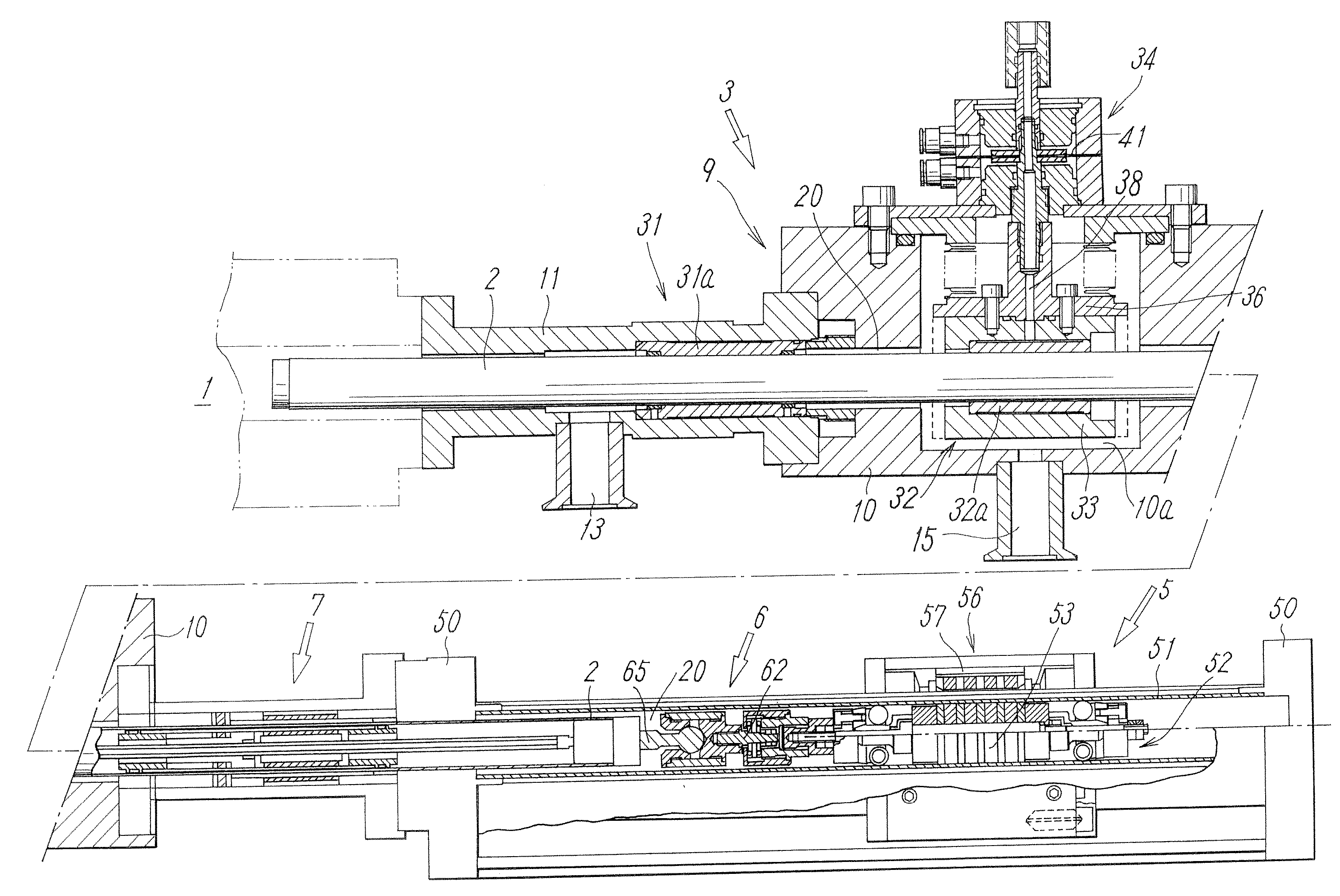
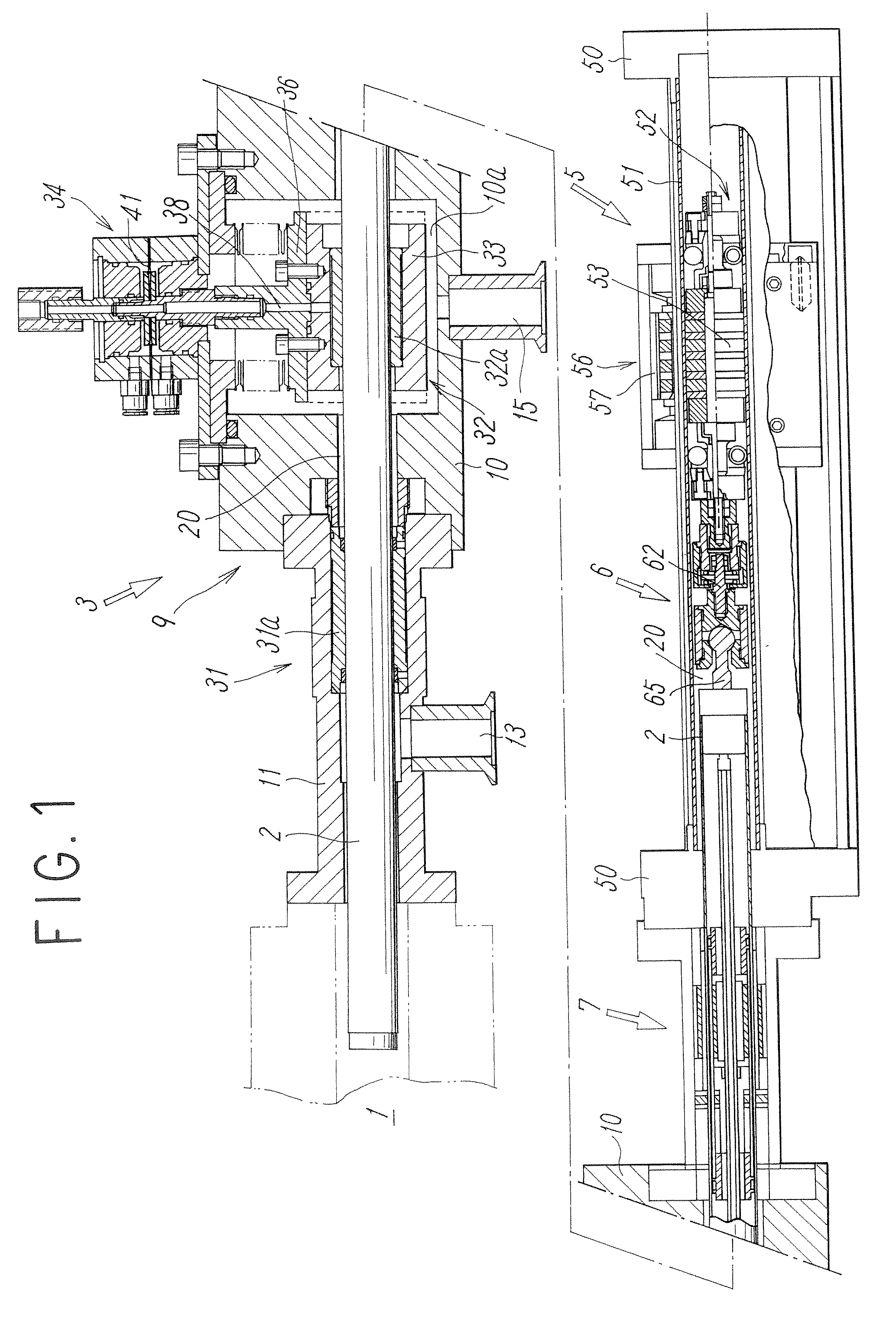
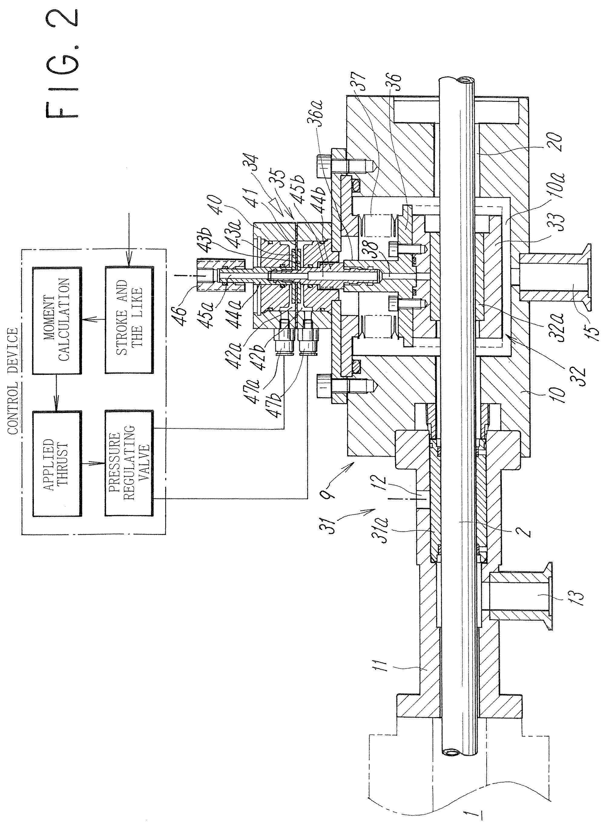
[0027]FIG. 1 shows an embodiment of a straight conveying device for vacuum according to the present invention. As can be seen from the figure, the straight conveying device for vacuum comprises in an outline manner a working rod 2 for horizontal driving for conveying in / out and the like of a work with respect to a vacuum process chamber 1 provided for manufacture of semiconductors and the like, and a tray (not shown) is mounted at the tip end of the rod 2 so as to drive the rod 2 in its axial direction, and also comprises a static-pressure gas bearing mechanism 3 for supporting the horizontally arranged rod 2, a magnet coupling type driving mechanism 5 for driving the rod 2 in its axial direction, a floating joint 6 for connecting an internal moving body 52 of the driving mechanism 5 and the rod 2, and a rotation suppression mechanism 7 for suppressing rotation of the rod 2.

[0028] The driving system including the rod 2 is arranged in a rod housing cylindrical portion 20 communicati...


PUM


Abstract

A working rod with a tip end extending into a vacuum process chamber and moving in the axial direction, two static-pressure gas bearings supporting the rod in the non-contact manner, and an internal moving body of a magnet coupling type driving mechanism driving the rod are housed in a rod housing cylindrical portion leading to the vacuum process chamber, and an exhaust portion by suction is provided at a part of the rod housing cylindrical portion so that the pressure of the rod housing cylindrical portion is lowered than the pressure of the vacuum process chamber by the exhaust from the exhaust portion.

Description

TECHNICAL FIELD [0001] The present invention relates to a straight conveying device for vacuum and more specifically to a conveying device for straight conveyance of a work used in a vacuum environment or clean environment. BACKGROUND ART [0002] As a straight conveying device which can respond to vacuum, such devices are known that is provided with a magnet coupling type non-contact transmission method at a driving force transmission portion and a contact support method such as a sliding bearing and a ball bush at a contact portion (See Patent Document 1, for example). [0003] However, when the contact portion is of a contact support type, there is a problem of a lowered work processing productivity due to limitation on a shift to a higher driving speed in order to avoid drop of cleanliness caused by dust generated with rise of a driving speed and of durability due to progress of bearing abrasion. [0004] Also, such a device is publicly known that a conveying rod is inserted into a va...

Claims


Application Information

Patent Timeline
IPC IPC(8): A24C5/18
CPCF16C2300/62H01L21/67742Y10S414/135B65G49/00B65G49/02
Inventor SATO, SOICHIABE, TAKASHIMIYASATO, EIKOTAKAHASHI, MIGAKUTSUNODA, MASAKIYO
Owner SMC CORP
Why Eureka
Try Eureka