
Dry type cleaning apparatus and dry type cleaning method

a cleaning method and equipment technology, applied in the direction of cleaning filter means, cleaning using liquids, manufacturing tools, etc., can solve the problems of large energy consumption of processes, high environmental impact, and reduced cleaning costs and environmental impact, and achieve the effect of efficient cleaning

Inactive Publication Date: 2007-05-17
RICOH KK
View PDF10 Cites 33 Cited by
  • Summary
  • Abstract
  • Description
  • Claims
  • Application Information

AI Technical Summary

Benefits of technology

The present invention provides a dry type cleaning apparatus and method that can efficiently clean various types of materials. The apparatus includes a cleaning tank with a porous member and a cleaning object inlet, an air supply / discharge unit, and a moving unit. The method includes guiding the cleaning tanks and using blowing and suction units to remove dust from the cleaning object. The apparatus and method can continuously clean objects and separate dust from the cleaning medium.

Problems solved by technology

Thus, reduction of cleaning costs and environmental impact is a major issue.
These processes consume large amounts of energy and have high environmental impact.
A dry type cleaning method employing air-blowing is insufficient for cleaning off toner having a high level of adhesion strength.
Accordingly, the cleaning objects may contact and damage each other.
Therefore, it is difficult to apply this technology to fragile resin products.
Therefore, cleaning objects cannot be continuously cleaned by this method.

Method used


Image

  • Dry type cleaning apparatus and dry type cleaning method
  • Dry type cleaning apparatus and dry type cleaning method
  • Dry type cleaning apparatus and dry type cleaning method

Examples


first embodiment

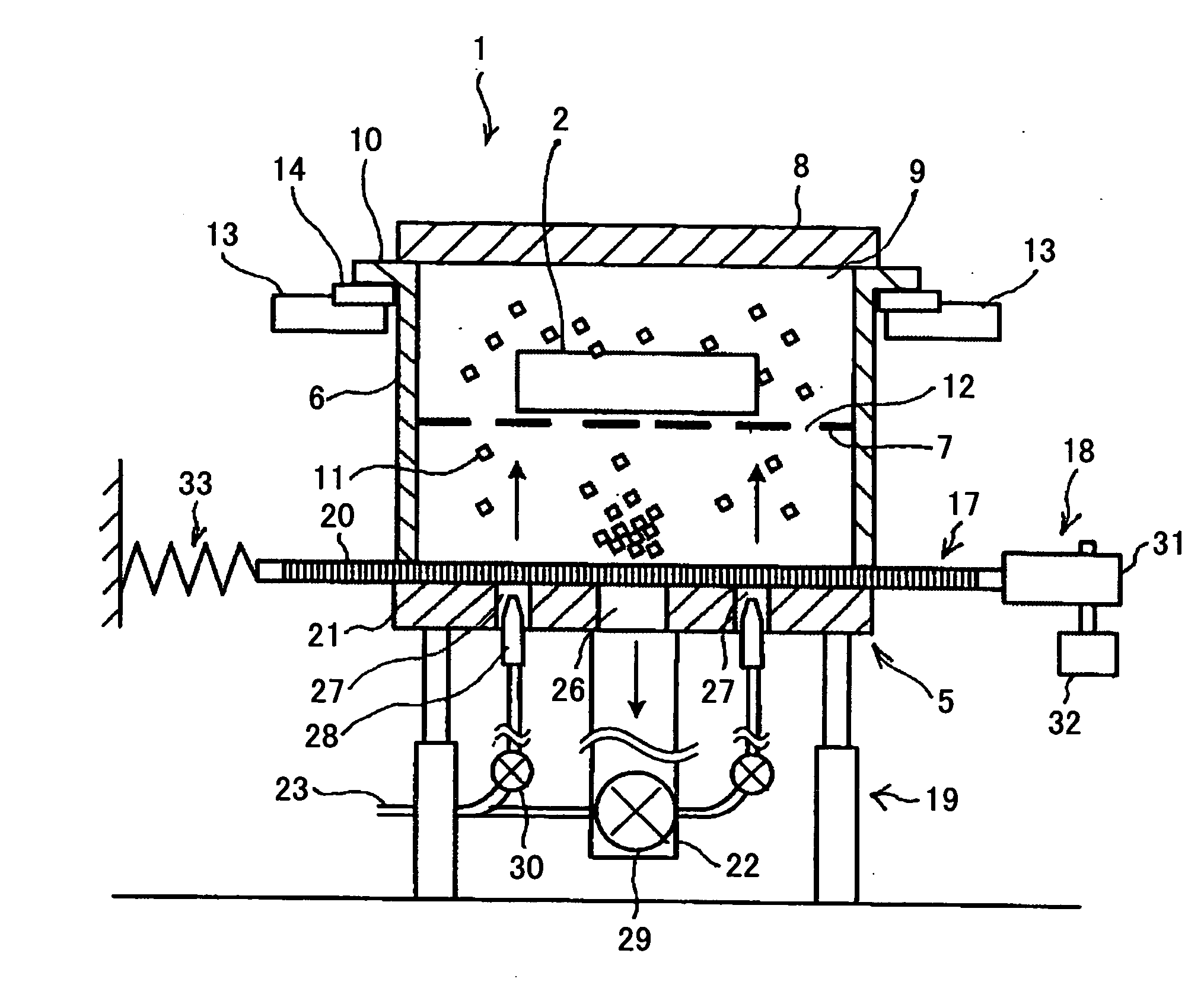
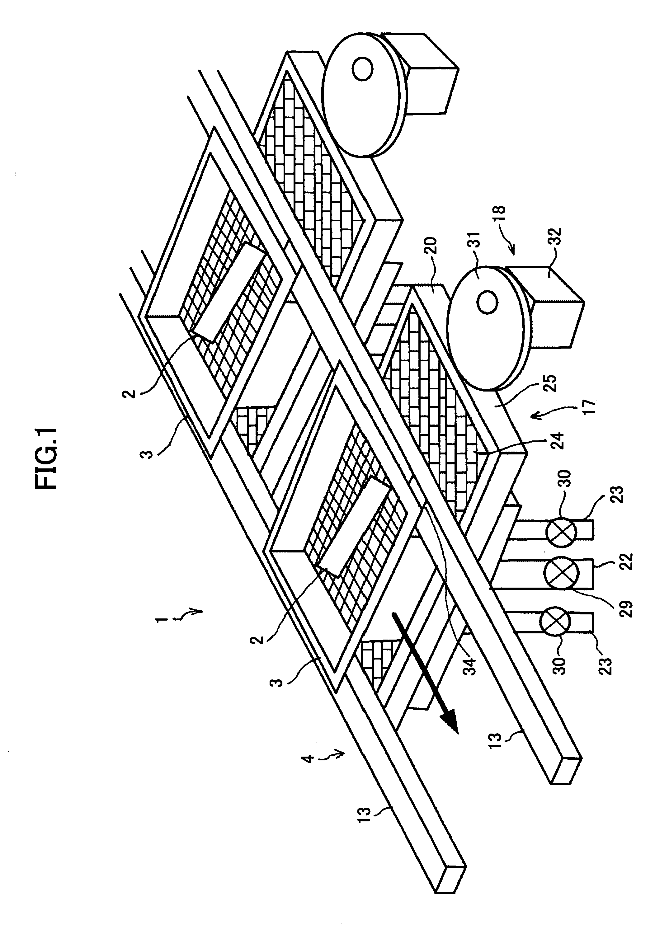
[0044]FIG. 1 is a schematic diagram of a dry type cleaning apparatus 1 according to the present invention. The dry type cleaning apparatus 1 removes dust such as toner adhering to a cleaning object 2, with a cleaning medium flowing on a high-speed airflow. The dry type cleaning apparatus 1 includes a cleaning tank 3, a cleaning tank moving unit 4, and a cleaning medium flying unit 5 (see FIG. 2).

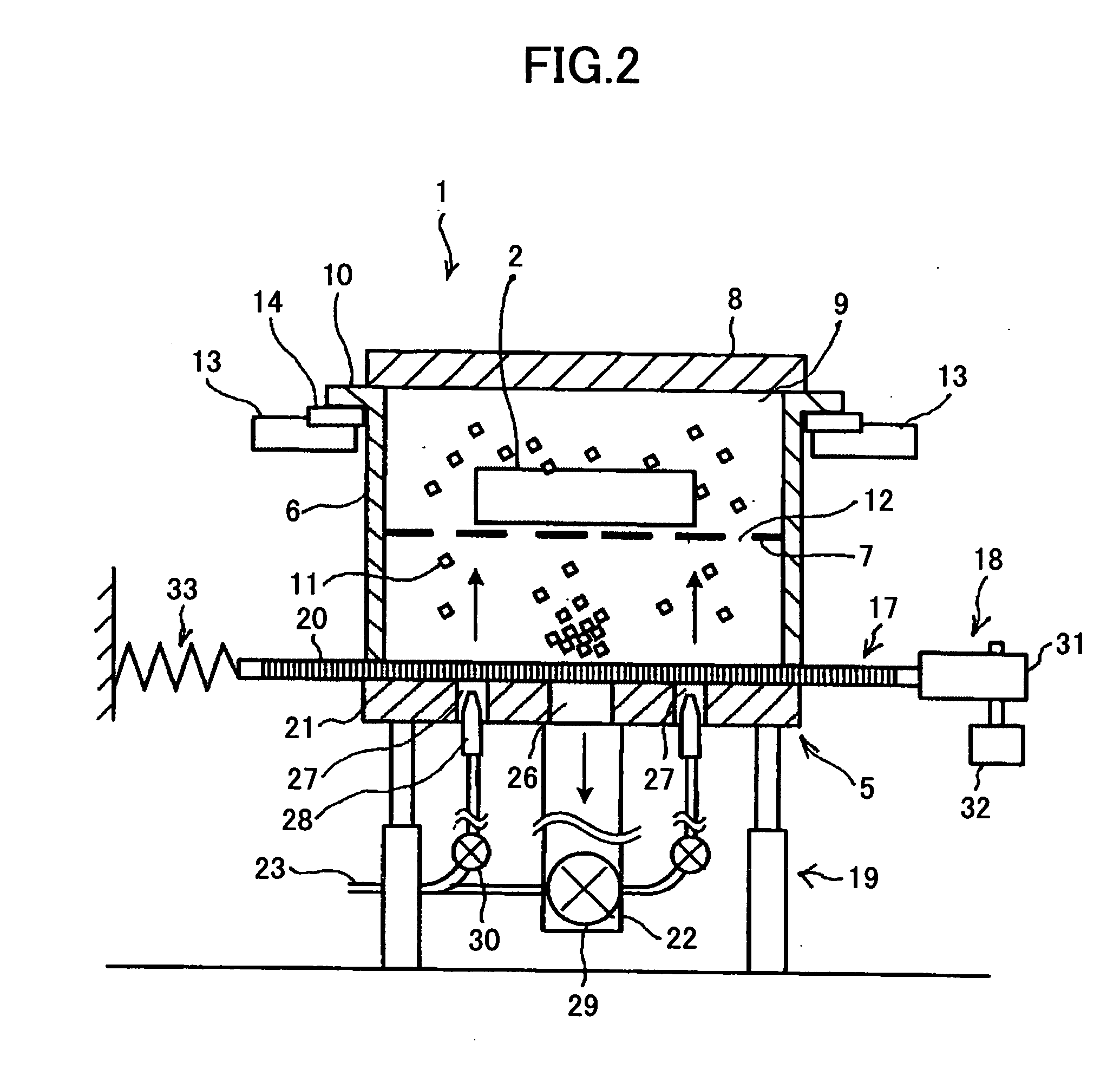
[0045]FIG. 2 is a cut-away side view of the dry type cleaning apparatus 1. The cleaning tank 3 includes a cleaning tank body 6, a cleaning object fixing unit 7, and a lid 8. A cleaning object inlet 9 is provided at the top of the cleaning tank body 6, from which the cleaning object 2 is inserted. The entire bottom of the cleaning tank body 6 is open. A guide part 10 that engages the cleaning tank moving unit 4 is provided at the periphery of the top edge of the cleaning tank 3. The cleaning object fixing unit 7 has plural openings 12 large enough to allow a cleaning medium 11 to pass through...

second embodiment

[0061] In a dry type cleaning apparatus 1a according to the present invention, the cleaning tank 3 is moved intermittently so that an area on the separating member 20 where air in the cleaning tank 3 is suctioned and an area on the separating member 20 where compressed air is blown into the cleaning tank 3 are switched. As shown in FIG. 6, the dry type cleaning apparatus 1a includes a linear guide 35 on which plural cleaning tanks 3a are mounted, plural suction pipes 22 and plural air pipes 23 connected to the linear guide 35, and a cleaning tank moving unit 36 for pressing the cleaning tanks 3a against the linear guide 35 and moving the cleaning tanks 3a.

[0062] As shown in FIG. 7, the cleaning tank body 6 of each cleaning tank 3a includes the cleaning object inlet 9 provided at the top thereof, from which the cleaning object 2 is inserted, and the lid 8 for sealing the cleaning object inlet 9. The bottom of the cleaning tank body 6 is covered with the porous member 24 including ma...

fourth embodiment

[0087] Another dry type cleaning apparatus is described next. FIG. 18A is a perspective view of a dry type cleaning apparatus 1c according to the present invention. The dry type cleaning apparatus 1c includes a cleaning tank 3b, a slide guide 61, the suction pipe 22 and the air pipes 23 connected to the slide guide 61, and a cleaning tank driving unit 62.

[0088] The cleaning tank 3b has a cylindrical shape having a certain length. Except for edges 63 on both sides of the cleaning tank 3b, the outer periphery is covered by the porous member 24 having many small holes and slits through which gas and dust can pass but the cleaning medium 11 cannot pass. Inside the cleaning tank 3b is provided a bag-shaped cleaning object fixing unit 7 having the plural openings 12 large enough to allow the cleaning medium 11 to pass through. Both of the edges 63 of the cleaning tank 3b have lids 64 that can open and close. Each of the lids 64 has a connecting part 65 including a groove and processes tha...


PUM


Abstract

A dry type cleaning technology is disclosed. Dust adhering to a cleaning object is removed with a cleaning medium caused to flow by a high-speed airflow. The removed dust is separated from the cleaning medium with a porous member including holes through which air, dust, and granular material can pass but the cleaning medium cannot pass. An area on the porous member where air is received to cause the cleaning medium to flow and an area on the porous member where air is received to suction the dust separated from the cleaning medium are switched.

Description

BACKGROUND OF THE INVENTION [0001] 1. Field of the Invention [0002] The present invention relates generally to dry type cleaning apparatuses and dry type cleaning methods for removing, by using solid cleaning media and without using water or solvents, dust and granular material, e.g., toner having average granular diameters of 5 μm through 10 μm. The toner is used in electrophotographic image forming apparatuses such as copiers and laser printers, where it adheres to various cleaning objects such as components having relatively complex shapes. More particularly, the present invention relates to a dry type cleaning apparatus and a dry type cleaning method with which cleaning objects can be continuously loaded and cleaned, thereby enhancing operability. [0003] 2. Description of the Related Art [0004] Manufacturers of office equipment such as copiers, facsimile machines, and printers are actively involved in recycling activities for the purpose of realizing a resource-recycling society...

Claims


Application Information

Patent Timeline
Patent Type & Authority Applications(United States)
IPC IPC(8): B08B7/04B08B5/04B08B3/00B08B1/20
CPCB08B5/00B08B5/02B08B7/02B24B31/003B24B31/108B24C3/26
Inventor FUCHIGAMI, AKIHIROOKAMOTO, YOICHISATOH, TATSUYA
Owner RICOH KK
Learn More