Projection three-dimensional display apparatus

a three-dimensional display and display technology, applied in the field of projection three-dimensional display apparatus, can solve the problems of the need for special glasses or training, so as to improve the contrast of display picture and prevent deterioration of picture quality and resolution in space projection

Inactive Publication Date: 2007-05-17
PANASONIC CORP
View PDF1 Cites 68 Cited by
  • Summary
  • Abstract
  • Description
  • Claims
  • Application Information

AI Technical Summary

Benefits of technology

[0012] The present invention is proposed to solve the above problems. It is an object of the invention to provide a projection-type three-dimensional display apparatus comprising a means for detecting the shake of a screen and for correcting and controlling a group picture of view point pictures to a proper position based on the detected result to improve contrast of a display picture so that the deterioration of picture quality and resolution in space projection can be prevented and a three-dimensional effect given, thereby giving reality sense as if there is the realities in a space.
[0014] According to the present invention, by detecting the shake of the screen and correcting and controlling the group picture of view point pictures to a proper position based on the detected result, the alignment error between the projection picture and the lens array is able to be 0.1 mm or less. As a result, the contrast of the display picture is improved so that the deterioration of picture quality and resolution in space projection can be prevented and a three-dimensional effect given, thereby giving reality sense as if there is the realities in a space.

Problems solved by technology

However, when viewing three-dimensional pictures using the above methods, special glasses or training is needed.
In principle, there is a problem that if the right-eye position and the left-eye position are deviated from a horizontal direction, the three-dimensional effect is ruptured because the picture including parallax of a horizontal direction is provided.
However, it causes troublesome problems that the size of the apparatus becomes large and a marker must be attached to the viewer in order to sense the position of the viewer's eye or face.
Therefore, there is a problem that when performing a three-dimensional display, the resolution of a two-dimensional display panel is degraded to 1 / 100 in resolution.
Upon considering that the highest resolution of the liquid crystal panel practically used until now is about 200 dpi, it is very difficult to realize a high picture quality of a three-dimensional picture display of the integral photography method using the liquid crystal panel or the plasma display panel.
If the alignment error between the projection picture and the lens array becomes large, image distortion imaged on a space by the lens becomes large so that the contrast of the picture displayed is degraded to deteriorate picture quality and resolution in space projection.
Thereby, it is difficult to stereoscopically display the picture so that reality sense cannot be given as if there are the realities in the space.
However, in the projection-type stereoscopic display apparatus, it is very difficult to completely fix the projection apparatus and the screen, and in general, the vibration of the screen fixed occurs due to a vibration in an installation place to make the projection picture projected by the projection apparatus vibrate so that it is impossible to obtain the alignment of the projection picture and the lens array.

Method used


Image

  • Projection three-dimensional display apparatus
  • Projection three-dimensional display apparatus
  • Projection three-dimensional display apparatus

Examples


embodiment 1

[0069] (Embodiment 1)

[0070] Hereinafter, a projection-type three-dimensional display apparatus of the present invention will be explained with reference to its practical aspect.

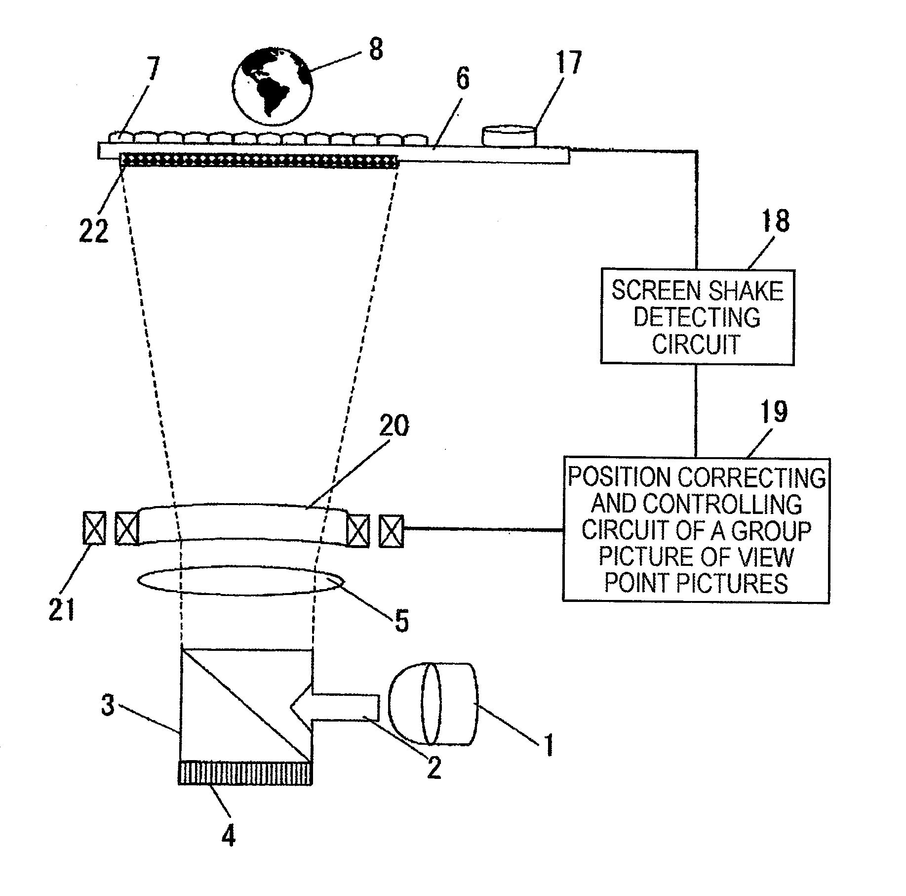
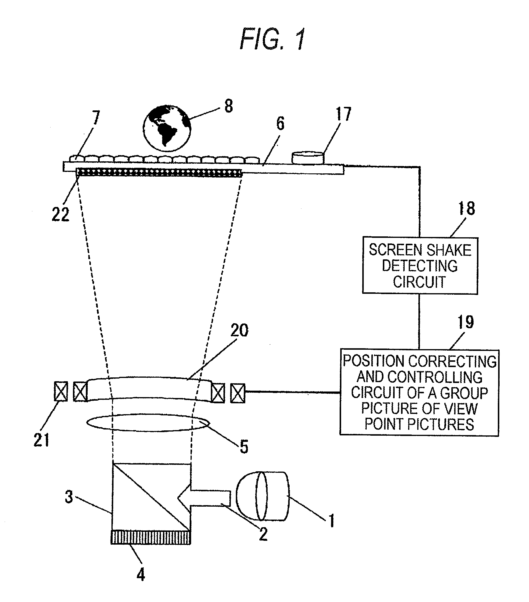
[0071]FIG. 1 is a view for explaining the embodiment 1 of the projection-type three-dimensional display apparatus of the present invention. In FIG. 1, after light 2 emitted from a light source 1 is incident on a polarizing beam splitter 3, only S-wave of the light is reflected from an interface of the polarizing beam splitter 3 and is incident on a projecting device 4 as a projecting means for controlling the shape of a projection picture. As the projecting device 4, a direct drive image light amplifier (D-ILA) available from Japanese Victor Co. can be used. The S-wave incident on the projecting device 4 is modulated in the inside of the projecting device 4 by the projection picture information to add the picture information. At this time, since the non-modulated light is reflected as the S-wave and returned...

embodiment 2

[0080] (Embodiment 2)

[0081] Hereinafter, a projection-type three-dimensional display apparatus will be explained with reference to an embodiment 2 of the present invention.

[0082]FIG. 4 is a view for explaining an embodiment 2 of a projection-type three-dimensional display apparatus of the present invention. In FIG. 4, light emitted from the light source 1 is light-collected by a condenser lens 28 to be incident on a transmission-type projecting device 29 as a projecting means for controlling a shape of a projection picture. As the transmission-type projecting device 29, a transmission-type liquid crystal may by used. The light incident on the transmission-type projecting device 29 is modulated by projection picture information in the inside thereof to add the picture information. The modulated light passes through a projecting lens 5 to be incident on a prism 30 for changing its projection angle and is then projected on an imaging screen 6 so that a projection picture 31 is imaged....

embodiment 3

[0089] (Embodiment 3)

[0090] Next, a projection-type three-dimensional display apparatus will be with reference to Embodiment 3 of the present invention.

[0091]FIG. 5 is a view for explaining the embodiment 3 of the projection-type three-dimensional display apparatus of the present invention.

[0092] In FIG. 5, light emitted from the light source 1 is light-collected by a condenser lens 28 to be incident on a transmission-type projecting device 29 as a projecting means for controlling a shape of a projection picture. As the transmission-type projecting device 29, a transmission-type liquid crystal may by used. The light incident on the transmission-type projecting device 29 is modulated by projection picture information in the inside thereof to add the picture information. The modulated light is projected on an imaging screen 6 via a projecting lens 5 to image a projection picture 31. Since the imaged projection picture 31 is a raytrace picture of an integral photography method, it ca...


PUM


Abstract

A screen for imaging a group picture of view point pictures is arranged and a screen shake detecting means and a means for correcting and controlling the group picture of the view point pictures projected on a screen to a proper position are provided.

Description

BACKGROUND OF THE INVENTION [0001] The present invention relates to a projection three-dimensional display apparatus capable of performing a three-dimensional display used in an image technology field, an amusement field, an entertainment field, an internet field, an information field, a multimedia field, a communication field, an advertisement and propaganda field, a medical field, an art field, an education field, a design supporting field, a simulation field, a virtual reality field, and the like. [0002] In past, as a means for displaying three-dimensional picture information, there have been a naked eye stereoscopic parallelism method viewing a right picture at a right eye and a left picture at a left eye with respect to two sheets of pictures with binocular parallax, a stereoscope method viewing the pictures using glasses attached with a liquid crystal shutter or different lenses for each of a right eye and a left eye, and an anaglyph method viewing binocular parallax pictures ...

Claims


Application Information

Patent Timeline
Patent Type & Authority Applications(United States)
IPC IPC(8): G03B21/14H04N13/363
CPCG03B21/14G03B21/625G03B35/24H04N13/0459H04N13/0497G03B2205/0007G03B2206/00G03B21/10G03B21/2073H04N13/363H04N13/398
Inventor KUBARA, TAKASHIHIRABARA, TAKASHI
Owner PANASONIC CORP
Why Eureka
Try Eureka