Oblique angle etched underlayers for improved exchange biased structures in a magnetoresitive sensor

a magnetoresitive sensor and underlayer technology, applied in the field of magnetoresitive field sensors, can solve the problems of catastrophic sensor failure, dramatically reducing so as to increase the pinning field of the pinned layer and improve the pinning field strength

Inactive Publication Date: 2007-05-17
WESTERN DIGITAL TECH INC
View PDF3 Cites 14 Cited by
  • Summary
  • Abstract
  • Description
  • Claims
  • Application Information

AI Technical Summary

Benefits of technology

[0019] The present invention provides a magnetoresistive sensor having improved pinning field strength. The sensor includes an AFM layer formed over an underla...

Problems solved by technology

A challenge that arises as a result of these decreased dimensions is that the pinning field strength decreases dramatically.
Other factors related to decreased sensor si...

Method used


Image

  • Oblique angle etched underlayers for improved exchange biased structures in a magnetoresitive sensor
  • Oblique angle etched underlayers for improved exchange biased structures in a magnetoresitive sensor
  • Oblique angle etched underlayers for improved exchange biased structures in a magnetoresitive sensor

Examples


Embodiment Construction

[0034] The following description is of the best embodiments presently contemplated for carrying out this invention. This description is made for the purpose of illustrating the general principles of this invention and is not meant to limit the inventive concepts claimed herein.

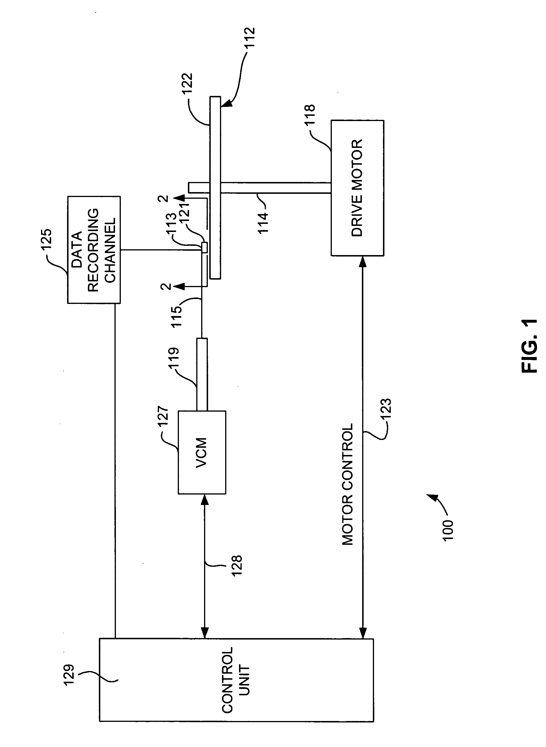
[0035] Referring now to FIG. 1, there is shown a disk drive 100 embodying this invention. As shown in FIG. 1, at least one rotatable magnetic disk 112 is supported on a spindle 114 and rotated by a disk drive motor 118. The magnetic recording on each disk is in the form of annular patterns of concentric data tracks (not shown) on the magnetic disk 112.

[0036] At least one slider 113 is positioned near the magnetic disk 112, each slider 113 supporting one or more magnetic head assemblies 121. As the magnetic disk rotates, slider 113 moves radially in and out over the disk surface 122 so that the magnetic head assembly 121 may access different tracks of the magnetic disk where desired data are written. Each sli...


PUM


Abstract

A magnetoresistive sensor having improved pinning field strength. The sensor includes a pinned layer structure pinned by exchange coupling with an antiferromagnetic (AFM) layer. The AFM layer is constructed upon an under layer having treated surface with an anisotropic roughness. The anisotropic roughness, produced by an angled ion etch, results in improved pinning strength. The underlayer may include a seed layer and a thin layer of crystalline material such as PtMn formed over the seed layer. The magnetic layer may include a first sub-layer of NiFeCr and a second sub-layer of NiFe formed there over. The present invention also includes a magnetoresistive sensor having a magnetic layer deposited on an underlayer (such as a non-magnetic spacer) having a surface treated with an anisotropic texture. An AFM layer is then deposited over the magnetic layer. The magnetic layer is then strongly pinned by a combination of exchange coupling with the AFM layer and a strong anisotropy provided by the surface texture of the underlayer. Such a structure can be used for example in a sensor having a pinned layer structure formed above the free layer, or in a sensor having an in stack bias structure.

Description

[0001] The present invention is related to patent application Ser. No. 11 / 097,543 filed on Mar. 31, 2005 entitled METHOD FOR MANUFACTURING A MAGNETIC READ SENSOR EMPLOYING OBLIQUE ETCHED UNDERLAYERS FOR INDUCING UNIAXIAL MAGNETIC ANISOTROPY IN A HARD MAGNETIC IN-STACK BIAS LAYER. [0002] The present invention is related to patent application Ser. No. 11 / 097,546 filed on Mar. 31, 2005 entitled A METHOD FOR MANUFACTURING A MAGNETIC READ SENSOR EMPLOYING OBLIQUE ETCHED UNDERLAYERS FOR INDUCING UNIAXIAL MAGNETIC ANISOTROPY IN A HARD MAGNETIC PINNING LAYER. [0003] The present invention is related to patent application Ser. No. 11 / 097,846 filed on Mar. 31, 2005 entitled A METHOD FOR MANUFACTURING A MAGNETIC READ SENSOR EMPLOYING OBLIQUE ETCHED UNDERLAYERS FOR INDUCING UNIAXIAL MAGNETIC ANISOTROPY IN HARD MAGNETIC BIAS LAYERS. [0004] The present invention is related to patent application Ser. No. 11 / 096,636 filed on Mar. 31, 2005 entitled MAGNETIC READ SENSOR EMPLOYING OBLIQUE ETCHED UNDERL...

Claims


Application Information

Patent Timeline
IPC IPC(8): G11B5/127
CPCB82Y10/00B82Y25/00G01R33/093G11B5/3909G11B5/3932G11B2005/3996
Inventor CAREY, MATTHEW JOSEPHCHILDRESS, JEFFREY ROBINSONFREITAG, JAMES MACMAAT, STEFANPINARBASI, MUSTAFA MICHAEL
Owner WESTERN DIGITAL TECH INC
Why Eureka
Try Eureka