
Lens for uniformly distributing light and optical emitting device using the same

a technology of light source and light emitting device, which is applied in the direction of semiconductor devices for light sources, lighting and heating apparatus, instruments, etc., can solve the problems of inconvenient use of conventional light emitting devices for lighting, insufficient brightness of front view, and irregular light distribution, so as to improve the quantity of light

Active Publication Date: 2007-05-17
SAMSUNG ELECTRONICS CO LTD
View PDF4 Cites 46 Cited by
  • Summary
  • Abstract
  • Description
  • Claims
  • Application Information

AI Technical Summary

Benefits of technology

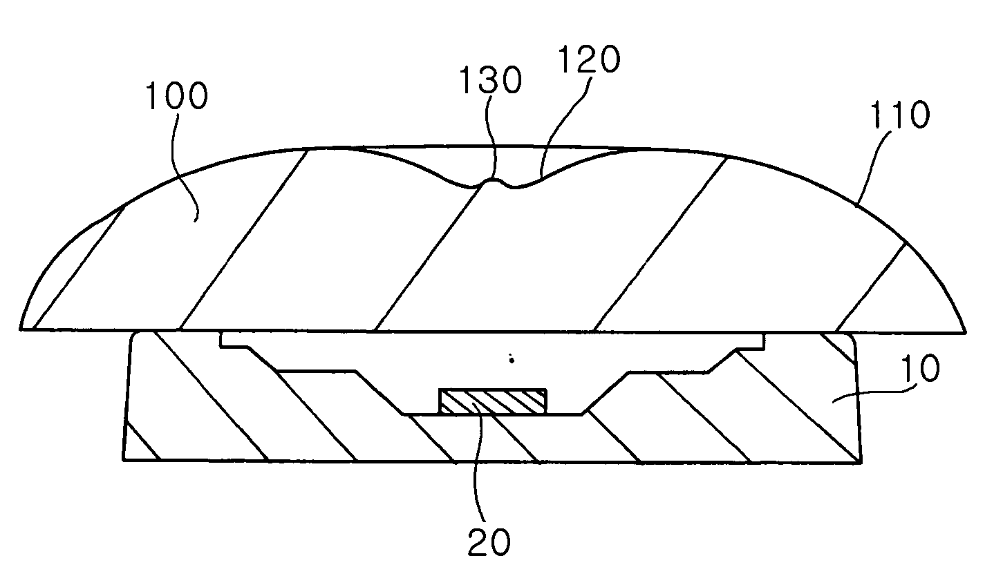
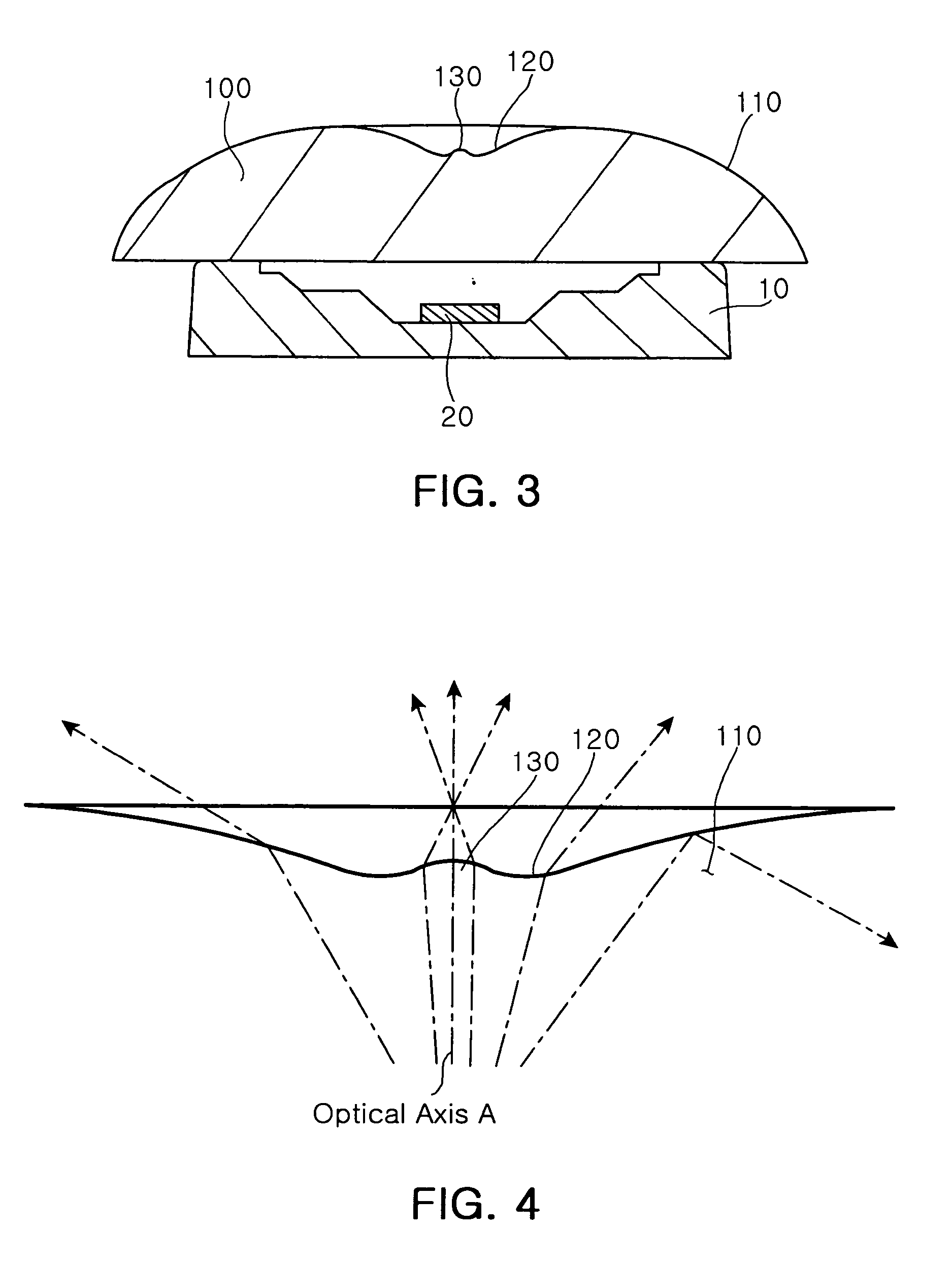
[0018] According to an aspect of the invention for realizing the object, the invention provides a lens. The lens includes a convex surface formed in an outer surface thereof facing away from a light source to uniformly distribute light emitted from the light source; a concave surface concaved inward from an inner region of the convex surface, around an optical axis; and a convex portion convexed outward from a central region of the concave surface, which the optical axis intersects, in order to enhance quantity of light around the optical axis.

Problems solved by technology

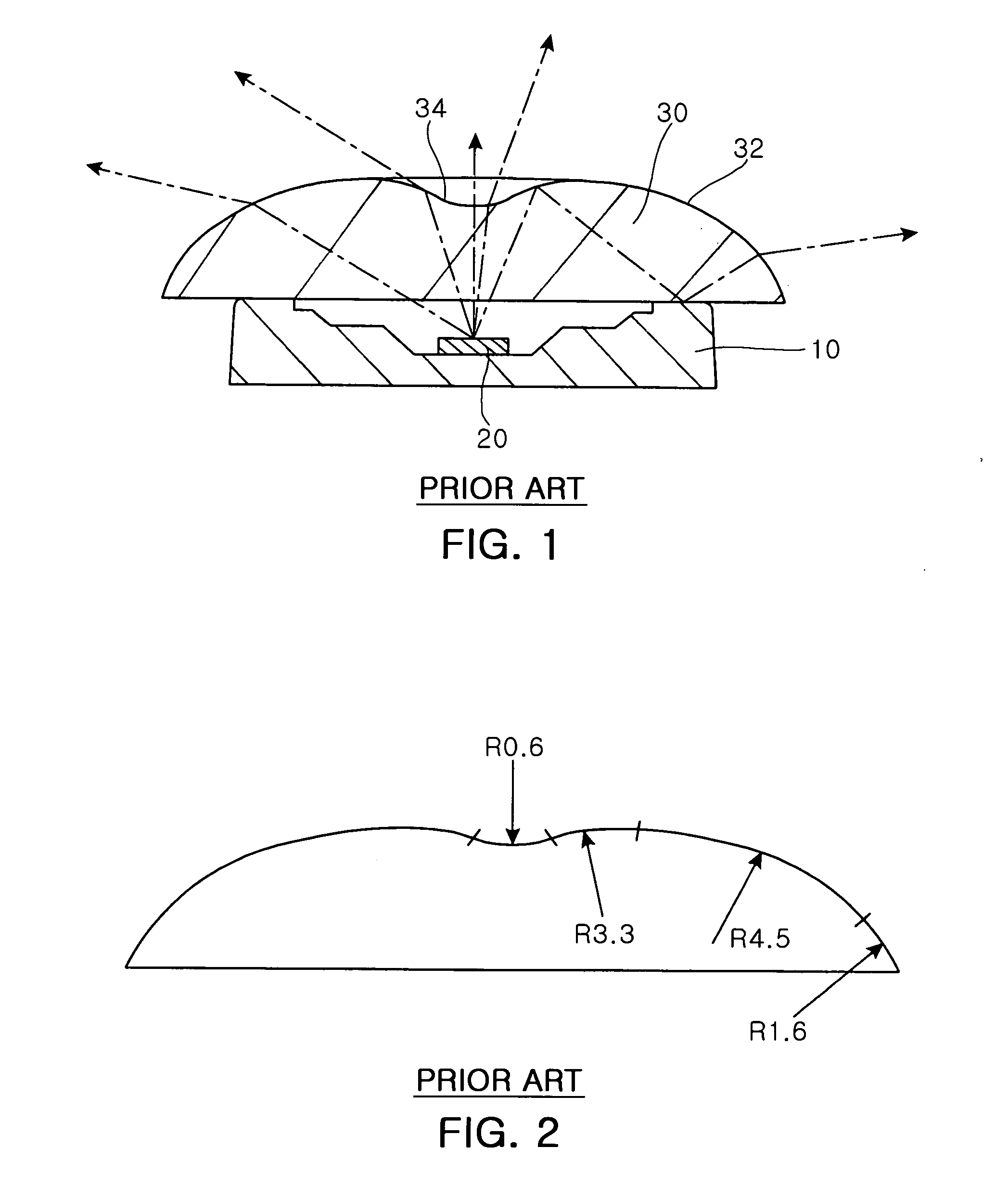
However, such a lens structure has a drawback in that light concentrates on a central region of the lens around the optical axis and thereby produces an irregular light distribution.
This makes it inconvenient to use the conventional light emitting device for the lighting.
In addition, where the conventional light emitting device is used for a display unit, it does not provide a bright display when seen from the front.

Method used


Image

  • Lens for uniformly distributing light and optical emitting device using the same
  • Lens for uniformly distributing light and optical emitting device using the same
  • Lens for uniformly distributing light and optical emitting device using the same

Examples


Embodiment Construction

[0036] The following detailed description will present embodiments of a lens and a light emitting device using the same according to the invention with reference to the accompanying drawings.

[0037] Referring to FIGS. 3 and 4, FIG. 3 is a vertical cross-sectional view illustrating a light emitting device of the invention, and FIG. 4 is a cross-sectional view illustrating a specific part of a lens of the invention.

[0038] As shown in FIG. 3, the light emitting device of the invention includes an LED 20 acting as a light source, an LED package base 10 where the LED 20 is seated and a lens 100 attached to the LED package base 10 to cover the LED 20.

[0039] The LED package base 10 has a concave geometry in an upper portion where the LED 20 is seated so that a slanted side wall of a recess of the LED package base 10 directs light beams emitted from the LED 20 toward the lens 100.

[0040] The operation and configuration of the LED 20 and the LED package base 10 are substantially the same a...


PUM


Abstract

A lens includes a convex surface formed in an outer surface thereof facing away from a light source to uniformly distribute light emitted from the light source; a concave surface concaved inward from an inner region of the convex surface, around an optical axis; and a convex portion convexed outward from a central region of the concave surface, which the optical axis intersects, in order to enhance quantity of light around the optical axis. The lens refracts light beams falling onto the respective areas thereof at different angles, thereby producing a uniform light distribution within a specific lighting range, but does not create a dark area around an optical axis.

Description

CLAIM OF PRIORITY [0001] This application claims the benefit of Korean Patent Application No. 2005-109031 filed on Nov. 15, 2005, in the Korean Intellectual Property Office, the disclosure of which is incorporated herein by reference. BACKGROUND OF THE INVENTION [0002] 1. Field of the Invention [0003] The present invention relates to a lens for uniformly distributing light emitted from a light source and a light emitting device using the same. More particularly, the lens of the invention has a concave area in an outer surface thereof, formed around the optical axis, and a protrusion in a central portion of the concave surface in order to prevent a dark area. [0004] 2. Description of the Related Art [0005] In general, a light emitting device is provided with a lens configured to distribute light emitted from a light source within a specific range. In the lens, an outer surface thereof facing away from the light source is curved convexly. [0006] With the outer surface of the lens curv...

Claims


Application Information

Patent Timeline
IPC IPC(8): G11B7/24H01L33/58
CPCG02F1/133603G02F2001/133607Y10S362/80F21Y2101/02F21V5/04G02B19/0014G02B19/0061F21Y2115/10G02F1/133607G02B3/00
Inventor JEONG, YOUNG- JUNELIM, SEOG HOKIM, BUM JINYANG, SUNG MIN
Owner SAMSUNG ELECTRONICS CO LTD
Learn More