

Toner-Particle Bearing Roller, Developing Device, And Image Forming Apparatus
a technology of developing device and toner particle bearing roller, which is applied in the direction of electrographic process apparatus, instruments, optics, etc., can solve the problems of toner particle deformation, toner particle breakage, and risk that toner particle, especially finely particulate toner particle, accumulates at the boundary between the bottom surface and the lateral surface, so as to suppress the deformation of toner particle
- Summary
- Abstract
- Description
- Claims
- Application Information
AI Technical Summary
Benefits of technology
Problems solved by technology
Method used
Image


Examples
fourth embodiments
Other Embodiments (Second to Fourth Embodiments)
[0184] A developing device or the like according to the present invention was explained by way of the foregoing embodiment, but the foregoing embodiment of the invention is merely for the purpose of elucidating the present invention and is not to be interpreted as limiting the present invention. The invention can of course be altered and improved without departing from the gist thereof and equivalents are intended to be embraced therein.
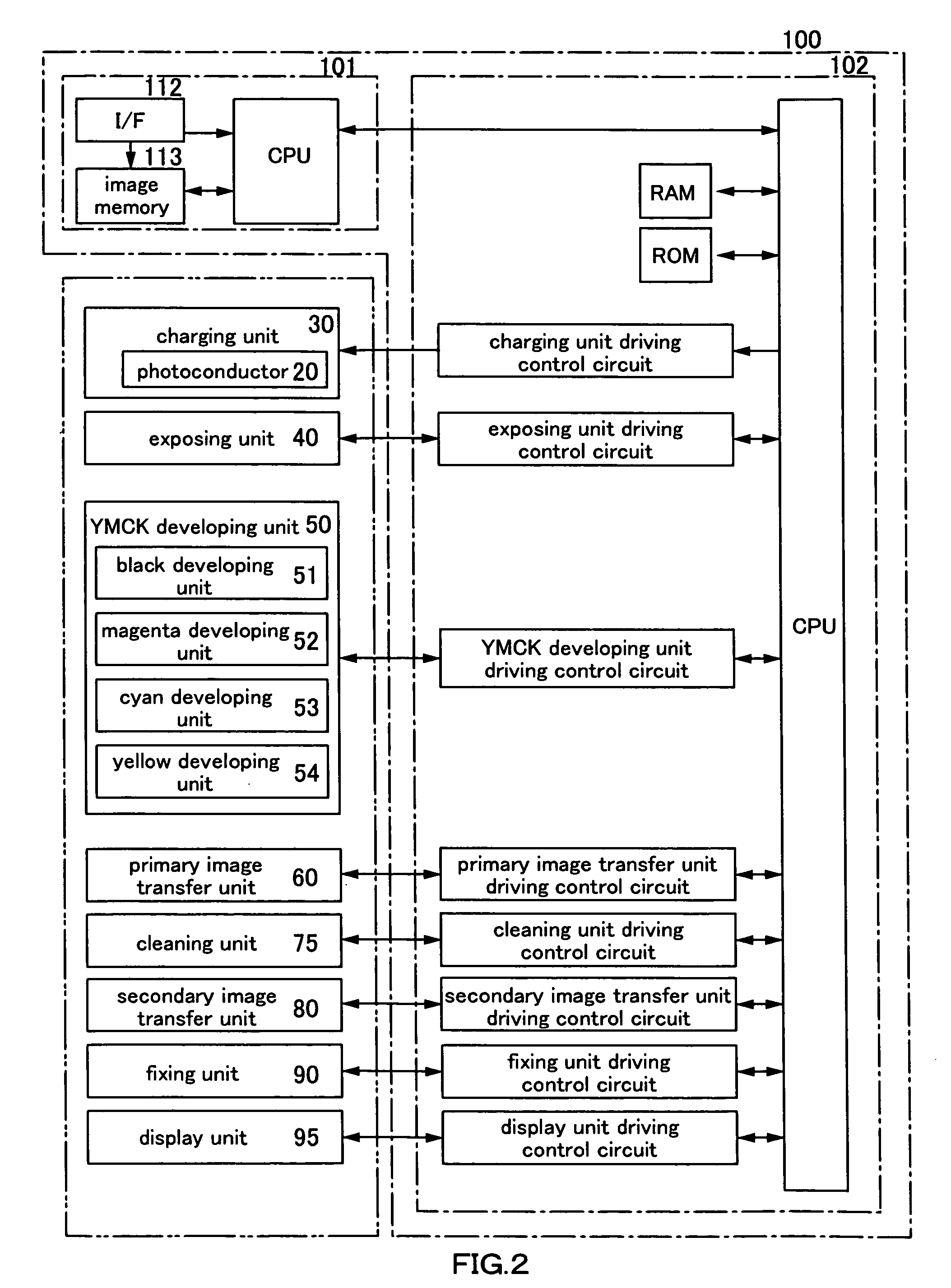
[0185] In the foregoing embodiment, an intermediate image transfer type full-color laser beam printer was described as an example of the image forming apparatus, however the present invention can also be applied to various other types of image forming apparatuses, such as full-color laser beam printers that are not of the intermediate image transfer type, monochrome laser beam printers, copying machines, and facsimiles.
[0186] Moreover, also the photoconductor is not limited to a so-called photoconduct...
second embodiment
Configuration Example of Developing Roller 510 of Developing Device According to Second Embodiment
[0198] Referring to FIG. 14, the following is an explanation of a configuration example of the developing roller 510 of the developing device according to a second embodiment. FIG. 14 is a diagram corresponding to FIG. 8 and is a schematic view showing the cross-sectional shape of the projection portions and depression portions according to the second embodiment.
[0199] As it becomes clear by comparing FIG. 8 and FIG. 14, the difference between the developing roller 510 of the developing device according to the second embodiment and the developing roller 510 of the developing device according to the first embodiment lies in the projection portion.
[0200] As shown in FIG. 14, the tip sections 1519a of the projection portion 1519 according to the second embodiment is provided with a rounding 1519d. Moreover, the radius of curvature of the rounding 1519d is set equal to or more than half...
third embodiment
Configuration Example of Developing Roller 510 of Developing Device According to Third Embodiment
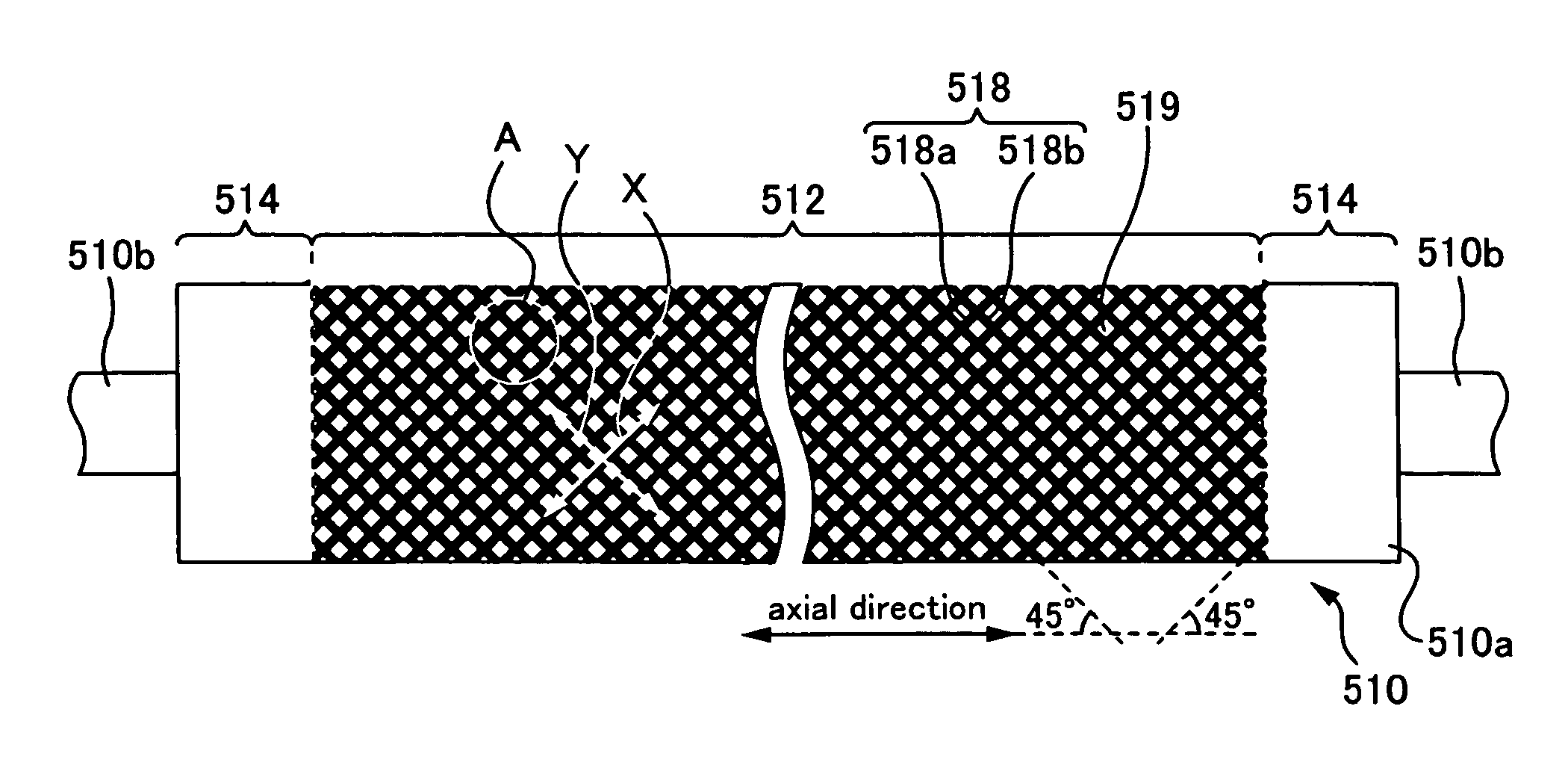
[0206] Referring to FIGS. 15 to 17, the following is an explanation of a configuration example of the developing roller 510 of the developing device according to a third embodiment. FIG. 15 is a schematic perspective view of the developing roller 510. FIG. 16 is a schematic front view of the developing roller 510. FIG. 17 is a schematic view showing the cross-sectional shape of the depression portions 2516 provided in the surface of the developing roller 510, showing a cross section taken along the direction marked by symbols X or Y in FIG. 16. It should be noted that for illustrative reasons, the scale of the depression portions 2516 and the like in FIGS. 15 to 17 is different than the actual scale.
[0207] The developing roller 510 of the developing device according to the third embodiment is a member made of an aluminum alloy, an iron alloy or the like, and transports the toner T bor...
PUM
 Abstract
Description
Claims
Application Information