
Capillary dispenser

a dispenser and capillary technology, applied in the field of capillary dispensers, can solve the problems of affecting the commercial use of capillary dispensers for cosmetic and personal care applications, affecting the quality of capillary dispensers, so as to achieve good protection against fluid leakage

Inactive Publication Date: 2007-05-17
CONOPCO INC D B A UNILEVER
View PDF55 Cites 18 Cited by
  • Summary
  • Abstract
  • Description
  • Claims
  • Application Information

AI Technical Summary

Benefits of technology

[0011] It has now been found that by equipping a capillary dispenser comprising a reservoir, a fluid feed line, and an applicator head, with (a) a fluid transfer zone in communication with the fluid feed line and the back of the applicator head, (b) a capillary overflow that communicates with the fluid feed line and / or the fluid transfer zone, and (c) a capillary control valve that regulates the passage of fluid and air in and out of the capillary overflow, there is provided a dispenser having good protection against fluid leakage over the dispenser pack life. Moreover, it has been found that such dispensers can be scaled in size to deliver desirable fluid payouts over relatively large contact surfaces, e.g., from 10 to 30 cm2, or greater, as well as over smaller contact surfaces. Additionally, the subject dispensers has been found to be particularly well suited to delivering fluid onto impermeable surfaces including, but not limited to, skin.

Problems solved by technology

Thus, dispensing from a capillary dispenser onto an impermeable surface (such as, for example, skin) may pose fluid payout issues different from those faced when the dispenser is intended for use on permeable surfaces (such as, for example, paper).
The problem of achieving sufficient fluid payout from a capillary dispenser may be exacerbated as the surface area of the applicator head and / or the dosage size is increased.
Achieving sufficient fluid payout may be one factor that has limited the commercial use of capillary dispensers for cosmetic and personal care applications.
Additionally, as dispensers are scaled up in size to achieve larger fluid payout, achieving adequate protection against fluid leakage can be increasingly difficult.
Moreover, larger dispensers may exacerbate the potential for trapping or stranding fluid in the dispenser.

Method used


Image

  • Capillary dispenser
  • Capillary dispenser
  • Capillary dispenser

Examples


Embodiment Construction

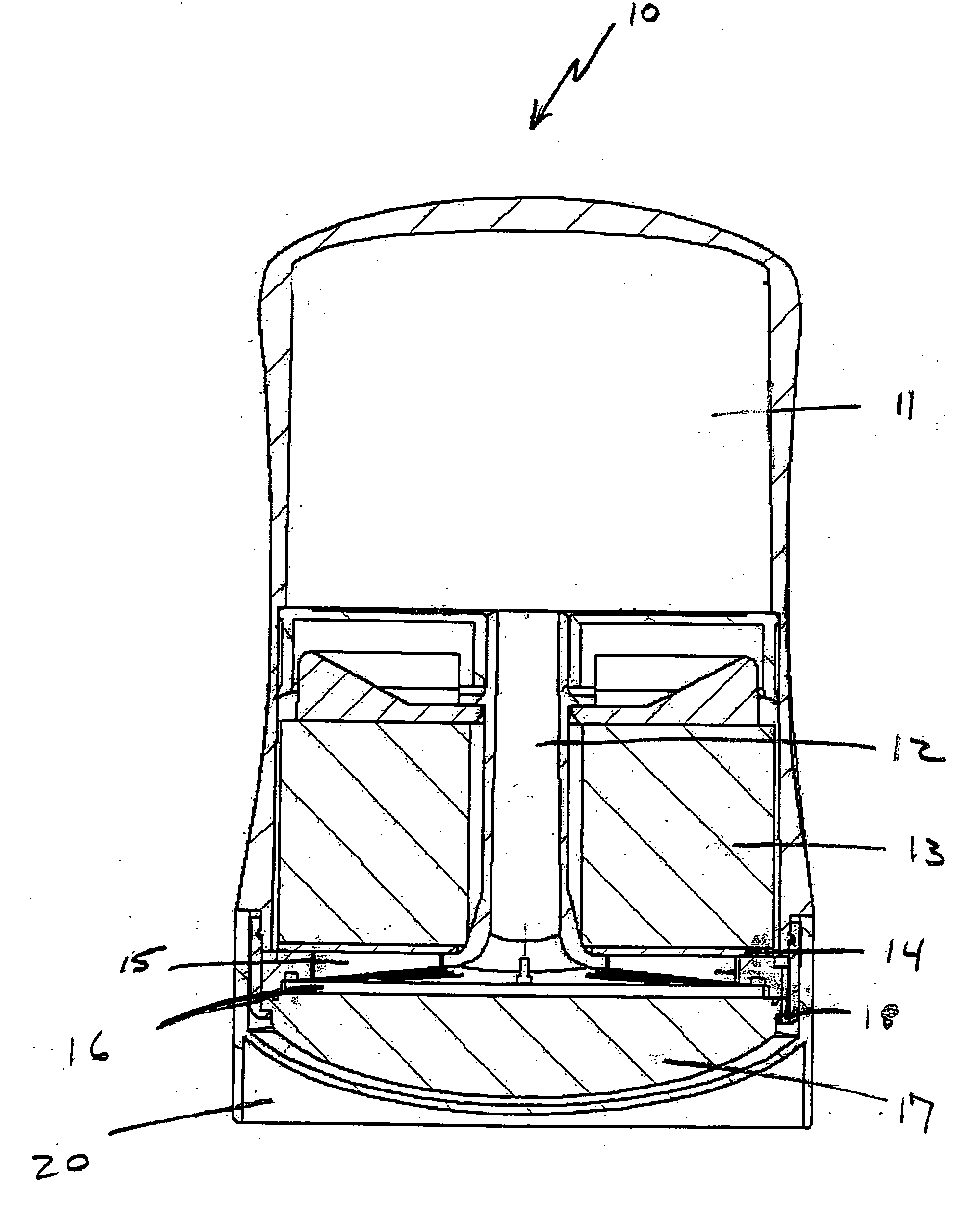
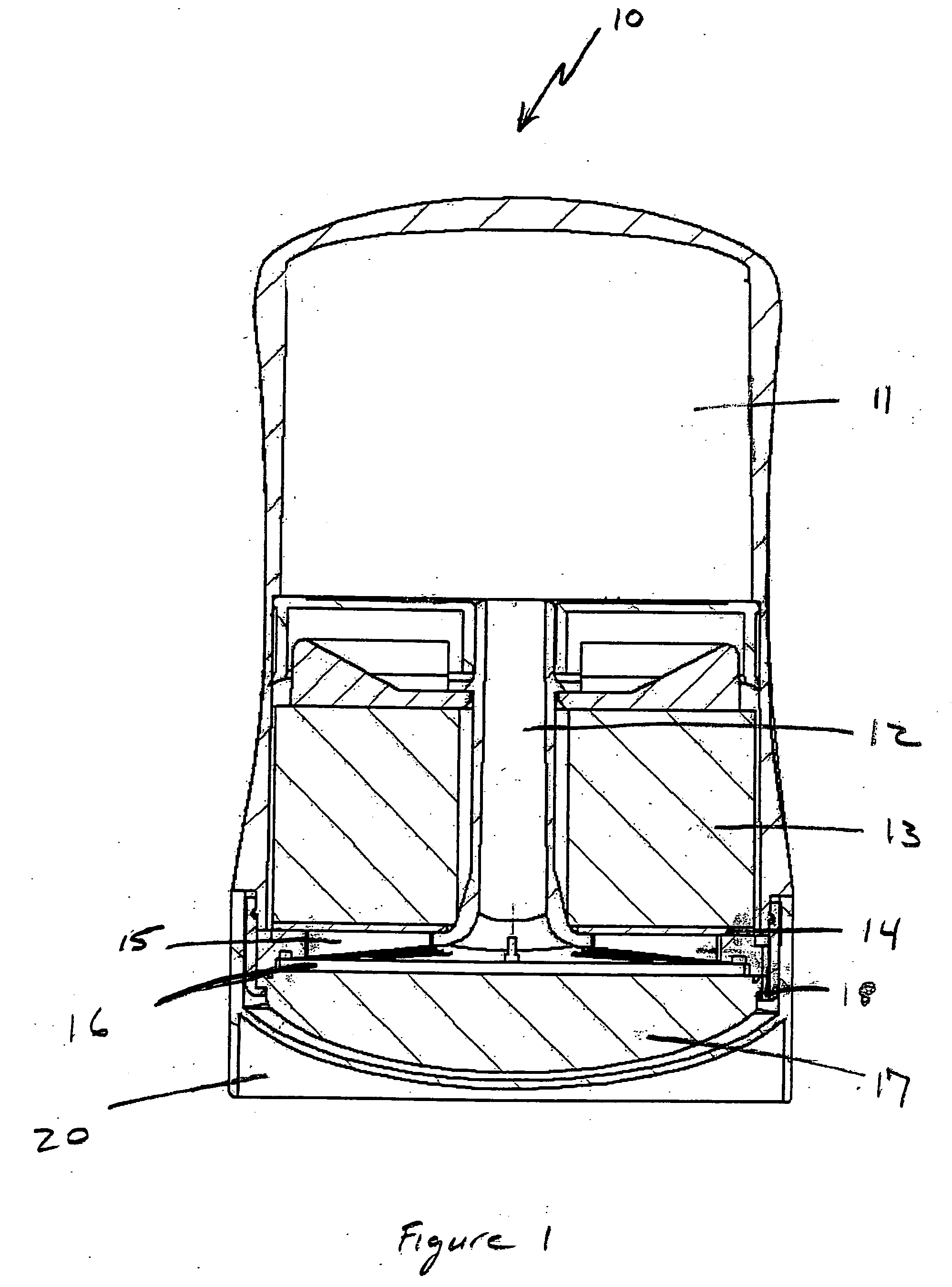
[0027] Throughout this specification, the terms “upper” and “lower” are used in relation to an orientation of the dispenser with the applicator head at its top and the reservoir at its bottom. The applicator head up / reservoir down orientation is also interchangeably referred to as the “upright”, “applicator head up” or “head up” orientation or position. In at least one embodiment, e.g., deodorant or antiperspirant dispensers, it is contemplated that dispensing of fluid may take place with the dispenser in an applicator head up orientation, however, in moving the applicator head across the underarm region, it should be recognized that the angle at which the applicator head makes contact with the skin may be widely variable. In at least one embodiment, it is contemplated that the dispenser may be stored in an “applicator head down” orientation, as shown in FIG. 1. In the context of this invention, unless otherwise indicated, throughout the subject specification and claims, reference t...


PUM


Abstract

Disclosed are fluid dispensers comprising: a) a fluid reservoir, b) a fluid feed line, c) a fluid transfer zone, d) a capillary overflow, e) a capillary control valve, and f) a porous applicator head, wherein: i) the fluid feed line communicates with the fluid reservoir and the fluid transfer zone; ii) the fluid transfer zone is intermediate to the porous applicator head and capillary overflow; iii) the capillary overflow is in communication with the transfer zone and / or the fluid feed line; and iv) fluid is drawn through the porous applicator head by means of capillary action; and v) the capillary control valve regulates the flow of fluid in and out of the capillary overflow.

Description

[0001] This application claims the benefit of U.S. Provisional Application No. 60 / 735,765 filed Nov. 12, 2005.FIELD OF THE INVENTION [0002] This invention relates to the application of fluids to a surface by means of capillary action and devices for doing the same. In particular, this invention relates to capillary devices suitable for use in applying liquid cosmetic compositions or liquid personal care compositions to the human body, e.g., the skin. BACKGROUND OF THE INVENTION [0003] Devices for applying cosmetic compositions to the body may be broadly divided into two types: contact applicators and non-contact applicators (e.g. spray applicators). The present invention is concerned with the former type of applicator and, in one embodiment of particular interest, to capillary dispensers for liquid cosmetic or personal care compositions. [0004] Capillary dispensers are commonly used in utensils such as writing instruments. U.S. Pat. No. 6,089,776, for example, discloses a fluid disp...

Claims


Application Information

Patent Timeline
Patent Type & Authority Applications(United States)
IPC IPC(8): B43K5/00
CPCA45D34/04A45D2200/1018A61M35/003
Inventor ERICKSON, GREGORY ALANPETERSON, ERIKWITZ, WOLFGANGHUNTER, ADAM J.
Owner CONOPCO INC D B A UNILEVER
Learn More