Artificial auditory tube

Inactive Publication Date: 2007-05-17
MORITA MASAHIRO
View PDF5 Cites 5 Cited by
  • Summary
  • Abstract
  • Description
  • Claims
  • Application Information

AI Technical Summary

Benefits of technology

[0031] The present invention as respectively defined above serves, by properly restoring the ventilatory and drainage functions of the eustachian tube, to provide the basic treatment of a variety of middle ear disorders caused

Problems solved by technology

This leads to symptoms such as a feeling of fullness in the ear, hearing loss, and autophony.
This disorder, in which collection of effusion is present in the middle ear cavity as a result of persistent negative pressure in the tympanic cavity, not only causes conductive hearing loss and a feeling of fullness in the ear due to the effusion that fills the tympanic cavity, but also render the patient susceptible to recurrent acute otitis media.
Further, a situation in which the tympanic cavity is kept under negative pressure chronically and irreversibly could cause adhesive otitis media, a very refractory disease in which the tympanic membrane adheres to the wall of the tympanic cavity, or otitis media with cholesteatoma, a disease in which the corneal squamous epithelium of the tympanic membrane grows in the middle ear cavity, which originally is free of epithelium, corroding, along with it, the surrounding bone.
However, the efficacy of these methods has not yet been objectively verified.
However, there still is

Method used


Image

  • Artificial auditory tube
  • Artificial auditory tube
  • Artificial auditory tube

Examples


example 1

[0087] The present invention is described in further detail below with reference to some typical examples. However, it is not intended that the present invention be limited to those examples.

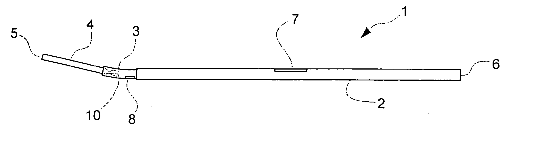
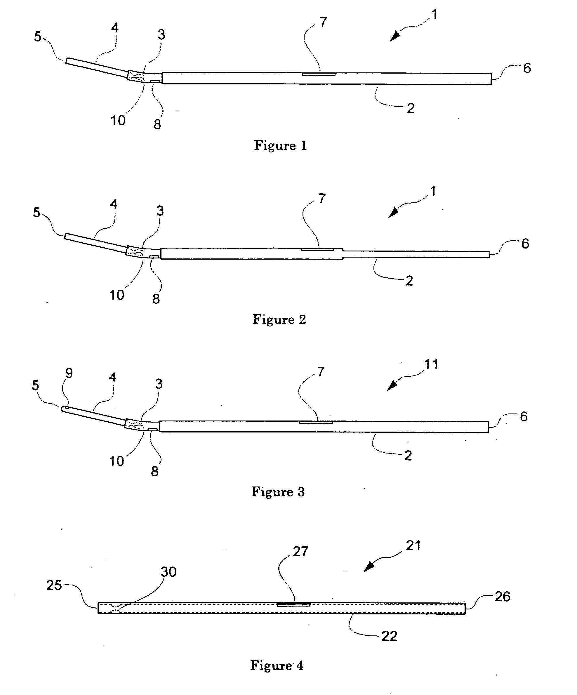
[0088]FIG. 1 illustrates a side view of Example 1 of the artificial auditory tube of the present invention. In the figure, the artificial auditory tube 1 consists of shaft a portion 2, which is a tubular portion having a relatively greater external cross-sectional dimension, an intermediate tubular portion 3, which also is a tubular portion but having a smaller external cross-sectional dimension than that of the former, and a distal tubular portion 4, which is a tubular portion having a still smaller external cross-sectional diameter. Any of these portions are circular in their cross sections. A lumen extends from the distal end to the proximal end of the artificial auditory tube 1, and the lumen is open to outside at the distal end 5 and the proximal end 6, respectively. In this example, the f...

example 2

[0093]FIG. 3 illustrates a side view of Example 2 of the artificial auditory tube 11. This example differs from Example 1 of the auditory tube only at and near the distal end. Thus, in this example, the distal end 5 is closed and an opening 9 is defined laterally in the tubular wall. The opening 9, which is in communication with the lumen, performs the same function as the opening at the distal end of the Example 1 of the artificial auditory tube 1. However, in Example 2, since the distal end 5 of the artificial auditory tube 11 is closed, a guide wire, when inserted into the lumen through the proximal end 6 for insertion into the patient's eustachian tube, will not stick out of the distal end 5 even if the external diameter of the guide wire is smaller than the internal diameter of the distal tubular portion 4, for the tip of the guide wire will abut on and be stopped by the closed distal end 5 of the artificial auditory tube 11. Therefore, this adds to the degree of freedom of the...

example 3

[0094]FIG. 4 illustrates a side view of Example 3 of the artificial auditory tube 21. This example, which consists of a tubular member 22 of a uniform external diameter of approximately 2.5 mm having a lumen that is open at the distal end 25 and the proximal end 26, is for use in the treatment of patulous eustachian tube. It is linear in the figure, but its distal portion may be bent as in Example 1. Its tubular wall is provided with an opening 27, at a position approximately 18 to 21 mm from the distal end 25 of the artificial auditory tube 21. It has a narrowed part 30 that is formed by a circular inner projection of the inner wall at a certain part of the lumen, and internal diameter of the narrowed part 30 is approximately 0.35 mm. The artificial auditory tube of this example is intended to be inserted, with its distal end being placed in the isthmus of the eustachian tube and facing inside of the cartilaginous eustachian tube, for the purpose of reducing, by clogging, the effec...


PUM


Abstract

Disclosed is an artificial auditory tube that is a therapeutic instrument useful for the treatment of eustachian tube dysfunction including stenosis of the eustachian tube (occlusion of the eustachian tube), patulous eustachian tube, closure defect of the eustachian tube, and “floppy tube”. The artificial auditory tube consists of a tubular body having a proximal end to be placed protruding out of the tympanic membrane within the external auditory canal and having a distal end to be inserted from the tympanic cavity into the eustachian tube and placed through the isthmus and facing the inside of the cartilaginous eustachian tube, the distal end and the proximal end communicating with each other through an internal cavity extending in the axial direction of the tubular body, the internal cavity opening to the outside through a first opening located in the distal end portion, and the external diameter falling in the range of from 0.35 to 3.0 mm, wherein the artificial auditory tube includes a second opening defined in the wall of the tubular body and positioned in the region ranging from 9 to 30 mm away from the distal end and communicating with the internal cavity of the tubular body.

Description

TECHNICAL FIELD [0001] The present invention relates to an artificial auditory tube to be inserted in the eustachian tube through the tympanic membrane. BACKGROUND ART [0002] The ear consists of the external ear, middle ear and inner ear. The external ear and the middle ear are partitioned with the tympanic membrane, which is located at the inner end of the external auditory canal. The middle ear consists of the tympanic cavity (middle ear cavity), i.e., the space enclosing in it auditory ossicles (the malleus, incus and stapes) that bridge between the tympanic membrane and the oval window, which leads to the vestibule of the inner ear, and the eustachian tube extending from the tympanic cavity and opens at the pharynx. The eustachian tube starts from the vestibule of the tympanic cavity (the tympanic opening of the eustachian tube), extends obliquely in the direction running from the upper-rear-lateral side to the lower-frontal-medial side, and opens in the lateral wall of the phar...

Claims


Application Information

Patent Timeline
IPC IPC(8): A61F11/00A61F2/04A61F2/18
CPCA61F11/008A61F11/30
Inventor MORITA, MASAHIRO
Owner MORITA MASAHIRO
Why Eureka
Try Eureka